200
Programming examples: Model helicopter
reference points; anything more elaborate is strict-
ly the province of experienced pilots. For the moment
you can safely accept the pre-set values of “L” = -30%
at the bottom end of stick travel and “H” = +30% at
the opposite end, although you may fi nd it necessary
to make slight corrections to these settings later.
Now switch back to the AR fl ight phase for a moment.
The set-up curve is disabled here, with the result that
the tail rotor servo no longer responds to collective
pitch commands (when the main rotor is not powered,
there is no torque to be corrected). All the other sub-
points are of no importance to us for the moment.
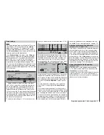
If your gyro features gain control from the transmitter
– unlike the type we are using in this example – you
can adjust gyro gain from the transmitter by assigning
one of the free INC / DEC buttons to the “
Gyro
” input
in the “Gyro” line of the menu:
»Control adjust« (page 80)
+100%
«normal »
ASY
SYM
ASY
SYM
0%
+100%
0.0 0.0
Cnt. 5
0%
0%
+100%+100%
+100%
+100%+100%
0.0 0.0
0.0 0.0
0.0 0.0
SEL
0%
SEL
+50%
–time+
Throt
Gyro
Input
free
free
free
7
Input
6
offset
–
8
5
Move the slider forward until the beeping stops, and
you reach the position marker at the aerial end of
the corresponding display. Now use the rotary cont-
rol to move to the
ASY
fi eld in the “Travel” column. At
this point set the maximum gain of the gyro to a va-
lue such as 50%, which represents a safe fi xed va-
lue when the button is at its forward end-point. You
will probably need to adjust the value in the course of
fl ight-testing. Additional notes on setting up gyros can
be found in the section “Gyro suppression” on pages
127 … 128.
To conclude the initial programming procedure, a few
words about the menu:
throttle servo is switched to a fi xed value which can
be set up as follows: press
ESC
to return to the menu
list. You will fi nd that certain new sub-menus now ap-
pear in the list, but only as long as you stay in the
auto-rotation phase. The new menus are:
Pitch
Thr setting AR
–90%
Tailrotoroffset AR
Gyro suppression
Swashplate rotation
0°
«Autorot»
=>
0%
0%
Swashplate limiter
off
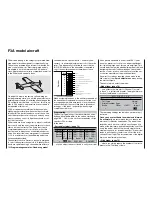
The important line here is “
Thr setting AR
”. The va-
lue on the right of this line should be set to either ap-
proxi125% or -125%, depending on the di-
rection of rotation of the throttle servo.
0°
«Autorot»
=>
0%
0%
SEL
–125%
Pitch
Thr setting AR
Tailrotoroffset AR
Gyro suppression
Swashplate rotation
If you are not sure of this, call up the »
Servo dis-
play
« menu by pressing the
HELP
button with the ro-
tary control pressed in.
This setting ensures that the motor is reliably stop-
ped in the auto-rotation phase (to cope with an emer-
gency). Later, when you have gained suffi cient expe-
rience to practise auto-rotation landings, the setting
should be changed to a value which provides a reliab-
le idle.
At present the remaining sub-menus are of no impor-
tance. Switch “AR” off, and we can move back to the
fi rst menu list.
Call up the “
Channel 1
t
ail rotor
” line, in which
you can set static torque compensation (DMA) for the
tail rotor. Here again, it is better to keep to just three
»Channel 1 curve« (page 92)
?
m
OU
T
P
U
T
--
+
1
100
–60%
–60%
Input
Curve
off
Point
Output
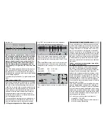
Channel 1 C U R V E
This function represents a sort of “convenient expo-
nential curve” for the collective pitch stick and the mi-
xer functions associated with it.
This curve should probably not be used at all initially.
If you do use it, be sure to use it “carefully”, and even
then not until the very last stage, i. e. when all the
other settings have been completed. It must not be
used to adjust the throttle / collective pitch function,
as the superimposed signals may produce unpredic-
table effects.
You have now completed all the helicopter-speci-
fi c adjustments which can be carried out in the calm
of your workshop. Further fi ne-tuning must now be
made with the model in fl ight. With a little luck, test-
fl ying will show the need for only minor (digital) trim
adjustments, which are – of course – stored automati-
cally by the transmitter.
If a major change is necessary, you should carry out
the mechanical correction required, or make adjust-
ments to the programmed settings we have just dis-
cussed.
Summary of Contents for mx-24s
Page 1: ...1...
Page 19: ...19 For your notes...
Page 35: ...35 For your notes...
Page 41: ...41 41 For your notes...
Page 57: ...57 For your notes...
Page 63: ...63 63 For your notes...
Page 69: ...69 69 For your notes...
Page 85: ...85 85 For your notes...
Page 99: ...99 For your notes...
Page 143: ...143 For your notes...
Page 191: ...191 For your notes...
Page 212: ...212 212 For your notes...
Page 213: ...213 213 For your notes...
Page 214: ...214 For your notes...
Page 216: ...216...


