48
Brief programming instructions
Brief programming instructions
for all fi xed-wing and helicopter programs
•
•
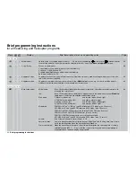
Dual Rate / Expo
Affects control functions aileron, elevator and rudder, or roll, pitch-axis and tail rotor. DUAL RATE and EXPO are
programmable separately for each fl ight phase.
DUAL RATE: altered control travel within the range 0 to 125% of normal control travel. Can be switched bet-
ween two settings in fl ight using switch, control switch or logical switch.
EXPO:
sets an exponential control curve without changing total travel. Variable rate of progression within
the range -100% to +100%; can be switched between two settings for each fl ight phase using
switch, control switch or logical switch.
Asymmetrical DUAL RATE or EXPO curves can be set up if the control switch is programmed to the stick centre
position in the »
Control switch
« menu, and the stick is moved in the corresponding direction.
86 / 88
•
•
Channel 1 curve
Defi nes the characteristic curve of the throttle / airbrake function or motor / collective pitch stick, separately for
each fl ight phase:
The momentary stick position of the transmitter control for the input channel is indicated on the screen by a verti-
cal bar. (“Input” shows the associated % value. “Output” gives the corresponding value of the control output).
Between the two extreme points “L” (low) and “H” (high) up to six additional curve reference points can be defi ned,
provided that you previously erase the default reference point “1” in the centre position. These points can be posi-
tioned along the control travel when “
Point
?
“ appears on the screen. Press the rotary control, then set the desi-
red “point” value in the highlighted fi eld using the rotary control. The points are automatically numbered from 1 to
6. To re-position points L, 1 … 6 or H subsequently, move the associated transmitter control to select the appropri-
ate reference point, or “jump” to it with the rotary control pressed in (trim point function). Press the
CLEAR
button
to erase points 1 … 6 again. Pressing the left-hand
ENTER
button switches a curve-rounding algorithm “on” and
“off”.
90 / 92
Switches
Switches
•
•
Switch display
When an external switch or control switch is operated, this display shows the associated switch number and
switch position.
93
•
•
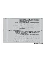
Control switch
Assign the transmitter controls 1 … 10 to the control switches 1 … 8 in column 2. Pressing
STO
(press the rota-
ry control) in column 3 stores the current control position as the switching point. Reverse the switching direction
in column 4, and assign a switch to override a control switch in column 5. Column 6 displays the switch status. By
default G1 is already programmed at -75% and G2 at +75% of the C1 stick travel.
94
•
•
Logical switch
Two switches (SW 1 … 8) and / or transmitter controls or even logical switches can be linked together logically
using “AND” or “OR” combinations. A total of eight logical switches can be defi ned.
“AND” function:
logical switch only closed when both individual switches are closed;
“OR” function:
logical switch closes when one of the two individual switches is closed.
97
Flight phases
Flight phases
•
Phase settings
Up to eight fl ight phases can be programmed and named individually for each model memory. The associated
100
Display
Menu
Brief description of menu and operating notes
Page
Summary of Contents for mx-24s
Page 1: ...1...
Page 19: ...19 For your notes...
Page 35: ...35 For your notes...
Page 41: ...41 41 For your notes...
Page 57: ...57 For your notes...
Page 63: ...63 63 For your notes...
Page 69: ...69 69 For your notes...
Page 85: ...85 85 For your notes...
Page 99: ...99 For your notes...
Page 143: ...143 For your notes...
Page 191: ...191 For your notes...
Page 212: ...212 212 For your notes...
Page 213: ...213 213 For your notes...
Page 214: ...214 For your notes...
Page 216: ...216...

