169
Programming examples: Fixed-wing model
Example 5
If, in contrast to the assumptions of the preceding Ex-
ample 4, your model features supplementary conven-
tional airbrakes, or even just airbrakes on their own,
these can also be included in the model’s control sys-
tem if you adopt the following programming procedu-
re:
Carry out the programming in the menus »
Model
type
«, »
Phase settings
« and »
Phase assignment
«
as described under Example 4. However, the settings
described in that section in the “
Brake settings
” sub-
menu of the »
Wing mixers
« menu are only relevant if
you also wish to use a Butterfl y (crow) system in par-
allel with the airbrakes.
With the settings described under Example 4, the
usual method of controlling the electric motor is adop-
ted, as is that for a butterfl y (crow) system, if approp-
riate. All we need to do now is add the programming
of the control system for an airbrake, connected in our
example to Output 8. This is accomplished by moving
to the menu …
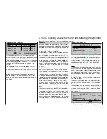
»Control adjust« (page 78)
… and
switching to the “
normal
” fl ight phase
. Hold
the rotary control pressed in, and move to the “Input
8” line. Select the
SEL
fi eld below the “Offset” column
and give the rotary control a brief press: the value
fi eld for Input 8 is now highlighted. Change the offset
value until the model’s airbrakes are “retracted” again:
0% +100%+100% 0.0 0.0
0% +100%+100% 0.0 0.0
0% +100%+100% 0.0 0.0
+100%+100% 0.0 0.0
SYM ASY
ASY
SYM
SEL
SEL
«Normal »
+100%
–time+
Input 5
free
Input 6
Input 7
Input 8
free
free
free
–
offset
A brief press on the rotary control returns you to the
SEL
fi eld; now select the left-hand
SEL
fi eld, move
to the “
Landing
” phase and press the rotary control
again briefl y. A new window now appears superim-
posed on the screen:
0% +100%+100% 0.0 0.0
0% +100%+100% 0.0 0.0
0% +100%+100% 0.0 0.0
+100%+100% 0.0 0.0
SYM ASY
ASY
SYM
SEL
SEL
«Landing»
–100%
–time+
Input 5
free
Input 6
Input 7
Input 8
fr
free
fr
–
offset
Move desired switch
or control adj.
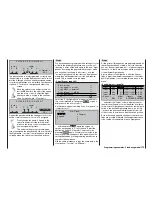
Move the C1 stick. As soon as it is detected, “Cnt. 1”
will appear on the screen instead of “free”:
0% +100%+100% 0.0 0.0
0% +100%+100% 0.0 0.0
0% +100%+100% 0.0 0.0
+100%
SYM ASY
ASY
SYM
SEL
SEL
«Landing»
0%
Cnt. 1
+100% 0.0 0.0
–time+
offset
Input 5
free
Input 6
Input 7
Input 8
free
free
–
Leave the Offset value in this fl ight phase at “0%”. Ho-
wever, you may need to reverse the prefi x of the tra-
vel setting in order to reverse the direction of the
transmitter control; this is effected by changing the
travel setting in the “-” column from +100% to
-100%.
Now we are virtually at our destination. Check your
programming in the »
Servo display
« menu: you will
fi nd that only “Servo 1” (speed controller) is controlled
in the “normal” phase, and only the airbrake “servo 8”
is controlled in the “Landing” phase, together with the
aileron and fl ap servos if present – exactly what we
were aiming for.
C1 stick doubling as electric motor and airbrake control
Summary of Contents for mx-24s
Page 1: ...1...
Page 19: ...19 For your notes...
Page 35: ...35 For your notes...
Page 41: ...41 41 For your notes...
Page 57: ...57 For your notes...
Page 63: ...63 63 For your notes...
Page 69: ...69 69 For your notes...
Page 85: ...85 85 For your notes...
Page 99: ...99 For your notes...
Page 143: ...143 For your notes...
Page 191: ...191 For your notes...
Page 212: ...212 212 For your notes...
Page 213: ...213 213 For your notes...
Page 214: ...214 For your notes...
Page 216: ...216...


