52
Clk 1 ... 3:
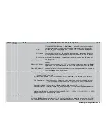
“Timer” column:
preset 0:00 means a count-up timer; time preset via rotary control (maximum 180 min
59 sec) generates a count-down timer (fl ashing colon in the basic display); the time is
highlighted after “zero”.
“Alarm” column:
timing and sequence of warning beeps when the alarm timer approaches and passes
through zero (max. 90 sec.).
Lap counter / time table: all you have to do is assign one of the ON / OFF switches SW 1 … 7 or the momenta-
ry switch SW8. In the basic display a “Timer” appears at the same time as the “counter”.
The timer is selected and assigned separately for each fl ight phase in the »
Phase set-
tings
« menu, where you will also fi nd a description of the individual timers.
Mixers
Mixers
•
Wing mixers
The revised wing mixer menu now provides for control of six-fl ap models. The range of actual functions which are
available depends on the type of model selected in the »
Model type
« menu.
Multi-fl ap menu:
fl ight phase specifi c setting of mixer functions for the ailerons (AILE) and the two pairs of
camber-changing fl aps (FLAP = middle pair of fl aps and FL2 = inboard pair of fl aps).
AI
:
in this line you set the effect of the aileron stick on the ailerons (AILE) and fl ap pairs
(FLAP, FL2).
Ail-tr:
this is where you set the effect of the aileron trim on the pairs of control surfaces. The
setting is also affected by the values you have set in the »
Stick mode
« menu.
Diff.:
aileron differential travel settings for all three pairs of control surfaces.
Fl.pos.:
fl ight phase specifi c fl ap positions for all three pairs of control surfaces.
FL
:
in this line you determine the effect of the fl ap control, as selected in the »
Transmitter
control adjust
« menu, on the ailerons and fl aps.
El
Fl:
this linear mixer sets the effect of the fl aps when an elevator command is given; the set-
ting is usually asymmetrical.
Brake settings:
the brake settings can only be set once for each model memory, and even then only if
you have selected “none” in the “Motor on C1” line of the »
Model type
« menu, or if “no”
has been selected for the fl ight phase concerned in the “Motor” column of the »
Phase
settings
« menu if you have selected “Throttle min. forward / back” in the “Motor on C1”
line.
In
the
»
Model type
« menu you can also select one of the inputs 1, 7, 8 or 9 as the con-
trol for the airbrake function. Inputs 7 and 8 can also be assigned a transmitter control in
the »
Transmitter control adjust
« menu, separately for each fl ight phase. The prefi xes
at the travel setting (+ or -) defi ne the direction of operation (forward or back); alterna-
tively the offset value in the “Brake” line of the »
Model type
« menu can be used.
110
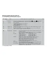
Brief programming instructions
for all fi xed-wing and helicopter programs
Brief programming instructions
52
Display
Menu
Brief description of menu and operating notes
Page
Summary of Contents for mx-24s
Page 1: ...1...
Page 19: ...19 For your notes...
Page 35: ...35 For your notes...
Page 41: ...41 41 For your notes...
Page 57: ...57 For your notes...
Page 63: ...63 63 For your notes...
Page 69: ...69 69 For your notes...
Page 85: ...85 85 For your notes...
Page 99: ...99 For your notes...
Page 143: ...143 For your notes...
Page 191: ...191 For your notes...
Page 212: ...212 212 For your notes...
Page 213: ...213 213 For your notes...
Page 214: ...214 For your notes...
Page 216: ...216...


