134
Program description:
Mixers
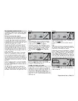
General notes regarding freely programmable mixers
The two menus »
Wing mixers
« and »
Helicopter mi-
xers
« contain a wide range of pre-programmed cou-
pling functions, as described on the preceding pages.
The basic meaning of mixers has already been ex-
plained on page 110, together with the principle on
which they work. In the following section you will fi nd
more general information relating to “free mixers”:
The
mx
-24s offers freely programmable mixers in
every model memory, whose inputs and outputs can
be selected to suit your exact requirements:
• eight linear mixers, numbered 1 to 8;
• four curve mixers, numbered 9 to 12.
These twelve mixers are certainly adequate for most
applications, but in any case they are invariably suffi -
cient when you incorporate the facilities of fl ight pha-
se programming. In the »
Mix active in phase
« menu
(see page 142) you can specify which of the twel-
ve mixers is active and disabled, separately for each
fl ight phase.
In the case of the “free mixers”, the signal present at
any
control function
(transmitter control 1 to 12) can
be assigned as the
input signal
of a “free mixer”. Al-
ternatively any switch can be assigned as the input si-
gnal using what is termed the “switch channel” (see
below). The signal present at the control channel and
passed to the mixer input is always infl uenced by its
own transmitter control
and
any control characteri-
stic you might have set, such as those selected in
the »
Dual Rate / Expo
«, »
Channel 1 curve
« and
»
Transmitter control adjust
« menus.
The mixer output acts upon a
freely selectable con-
trol channel
(1 to max. 12, depending on the type of
receiver). Before the signal is passed to the associa-
ted servo the only infl uences which can act upon it
are those defi ned in the »
Servo adjustment
« menu,
i. e. the servo reverse, neutral point offset, servo tra-
vel and servo travel limit functions.
One
control function
can be set up to affect several
mixers simultaneously, if, for example, several mixers
are to be arranged to work in parallel. Conversely it is
possible for several mixers to affect one and the same
control channel
. Particularly in the latter case, howe-
ver, it is very important to ensure that the servo con-
cerned does not strike its mechanical end-stops when
several mixer signals accumulate to an excessive ex-
tent. For safety’s sake it may well be sensible to set
an appropriate travel limit in the »
Servo adjustment
«
menu in such cases.
For more complex applications it is even possible to
connect multiple mixers in series: in this case it is
not the (transmitter) signal at the “output” of a control
function which forms the input signal of the “series-wi-
red” mixer, but the (mixed) signal “further back” at the
“input” of a
control channel
. The following description
of the free mixers includes several examples of such
arrangements.
In software terms the freely programmable mixer is
always switched on by default, but it is possible to as-
sign an optional ON / OFF switch to the mixer. Howe-
ver, since there are so many functions to which swit-
ches can potentially be assigned, you should take
care not to assign too many functions to any particu-
lar switch.
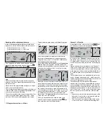
The important mixer parameters are …
… the
mixer ratio
, which defi nes the extent to which
the input signal acts on the output of the control
channel which is programmed as the mixer output.
If you are using linear mixers, the mixer ratio can
be set symmetrically for both sides of centre, or
asymmetrically. Curve mixers can also be confi gu-
red by defi ning up to eight reference points to suit
your application; this enables you to implement ex-
tremely non-linear curves.
… the
neutral point
of a mixer, which is also termed
the “offset”.
The offset is that point on the travel of a transmit-
ter control (stick, proportional control or switch) at
which the mixer has no infl uence on the control
channel defi ned as its output. Normally this is the
centre point of the transmitter control or switch,
but the offset can be placed at any point on the
control’s travel. Since there are no restrictions on
the design of the curve mixers, setting a mixer
neutral point only makes sense with the eight line-
ar mixers.
If you do not wish the corresponding mixer output
or control channel to respond to its normal transmit-
ter control – as, for example, in the case of Output 1
and a model glider not fi tted with airbrakes – then it
is possible to separate the transmitter control from
the control channel of the mixer output with a simple
button-press in the »
MIX only channel
« menu (see
page 142). Here again, the following menu descripti-
on provides an explanatory example of the function.
Switch channel “S” as mixer input
Occasionally a constant control signal is all that is re-
quired as the mixer input; a typical application would
be slight “up-elevator” trim when the parallel-connec-
ted aero-tow release is closed.
In this case a switch is assigned both to the aero-tow
release and the mixer; it is then used not only to open
and close the release, but also to pass the desired
trim signal to the elevator via the mixer ratio. To iden-
tify this special arrangement, this mixer input control
function in the program is designated “S” for “Switch
channel”.
Summary of Contents for mx-24s
Page 1: ...1...
Page 19: ...19 For your notes...
Page 35: ...35 For your notes...
Page 41: ...41 41 For your notes...
Page 57: ...57 For your notes...
Page 63: ...63 63 For your notes...
Page 69: ...69 69 For your notes...
Page 85: ...85 85 For your notes...
Page 99: ...99 For your notes...
Page 143: ...143 For your notes...
Page 191: ...191 For your notes...
Page 212: ...212 212 For your notes...
Page 213: ...213 213 For your notes...
Page 214: ...214 For your notes...
Page 216: ...216...


