background image

135

Program description: 

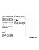
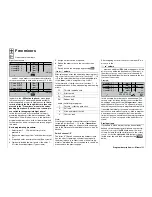
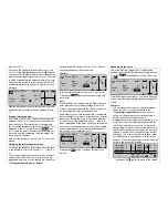
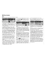
 Mixers

Free mixers

Linear and curve mixers

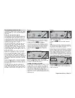
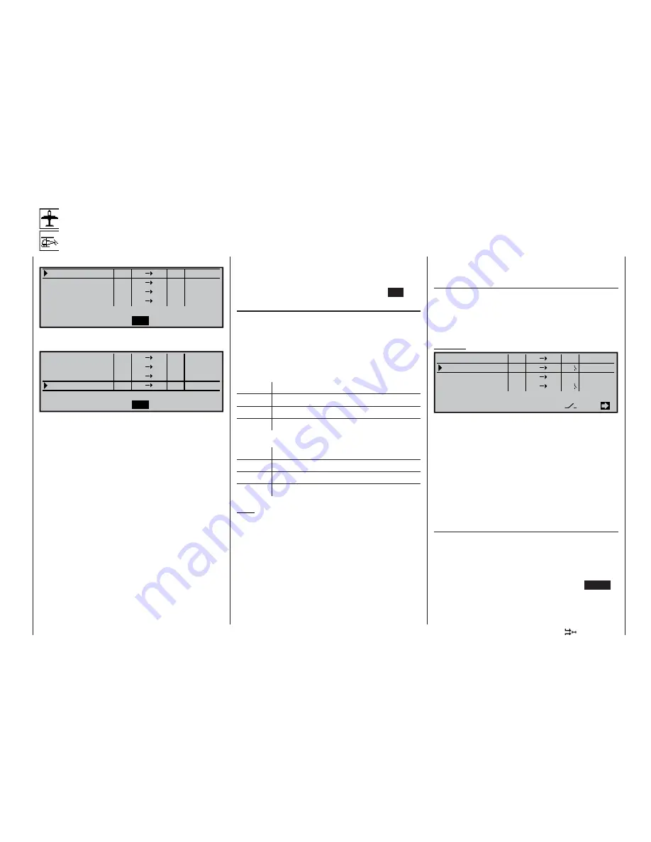
Eight linear mixers …

LinearMIX

type

SEL

SEL

??

??

- - - -
- - - -
- - - -
- - - -

??
??
??

??
??
??

1

LinearMIX
LinearMIX
LinearMIX

2
3
4

from

to

Adjust

… and four curve mixers for non-linear characteristic 
curves are available in each model memory (1 to 40):

SEL

SEL

??

??

- - - -
- - - -
- - - -
- - - -

??
??
??

??
??
??

type

from

to

Adjust

Curve MIX  9
Curve MIX10
Curve MIX11
Curve MIX12

In addition, the »

MIX active in phase

« menu (page 

142) enables you to activate and disable particular 
mixers separately for specifi c fl ight phases. 

In the in-

terests of clarity the blocked mixers are then sup-
pressed in the “Free mixers” menu in the corres-
ponding fl ight phase. If a mixer is not shown, ple-
ase switch to the appropriate fl ight phase!

In this fi rst section we will concentrate on the pro-
gramming procedure for the fi rst screen page of the 
“free mixers”. We will then move on to the method of 
programming mixer ratios, both for linear mixers and 
curve mixers, as found on the second screen page of 
this menu.

Basic programming procedure:

1.  Select mixer 1 … 12 with the rotary control 

pressed in.

2.  Defi ne the mixer input “from” and the mixer output 

“to”.

3.  If required, enter a serial mixer link (Type column).

4.  Optionally: include the trim levers of the sticks 1 … 

4 for the mixer input signal (Type column).

5.  Assign a mixer switch if required.

6.  Defi ne the mixer ratios on the second screen 

page.

7.  Switch back to the fi rst page by pressing 

ESC

.

“from …” column

After selecting a mixer line and briefl y pressing the ro-
tary control, enter one of the control functions 1 … 12 
or S in the selected mixer line in the highlighted fi eld 
of the “

from

” column, using the rotary control.

In the interests of clarity, the control functions 1 … 4 
are abbreviated as follows when dealing with the wing 
mixers:

C1

Throttle / airbrake stick

AI

Aileron stick

EL

Elevator stick

RU

Rudder stick

… and in the Helicopter program:

1

Throttle / collective pitch stick

2

Roll stick

3

Pitch-axis (elevator) stick

4

Tail rotor stick

Note:
Don’t forget to assign a transmitter control to the se-
lected control function 5 … 12 in the »

Transmitter 

control adjust

« menu, as all inputs (with one excep-

tion in the “Helicopter” model type) are set to “free” by 
default.

Switch channel “S”

The letter “S” (Switch channel) in the “

from

” column 

has the effect of passing a constant input signal to 
the mixer input, e. g. in order to add a little more “up-
elevator” trim when the aero-tow release is closed, as 
mentioned on the previous page.

After assigning a control function or the letter “S” we 
move on to the …

“… to” column

… where an additional 

SEL

 fi eld now appears. At this 

point you can defi ne the destination of the mixer, i. e. 
the mixer output, as one of the control channels. At 
the same time additional fi elds also appear in the bot-
tom line of the screen.

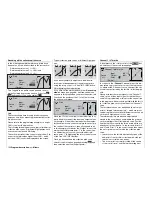
Example:

SEL

EL

6

=>
=>

C1

8

S

EL
10
EL

Tr

4I

C4

7

on
off

=>
=>

SEL

SEL

SEL

LinearMIX

type

1

LinearMIX
LinearMIX
LinearMIX

2
3
4

from

to

Adjust

In this example four mixers have been defi ned. The 
second mixer is already familiar to us from the “Bra-
ke settings” sub-menu of the »

Wing mixers

« menu 

under the name “Elev. curve”. As a general rule you 
should always use these pre-programmed mixers fi rst 
if possible. Admittedly, if you need asymmetrical mi-
xer ratios on both sides of centre, or wish to program 
a non-linear curve, or need to offset the mixer neu-
tral point, then you should leave the pre-programmed 
mixers at “0%” and set up one of the free mixers in-
stead.

Erasing mixers

If you need to erase a mixer that you have already 
defi ned, select the appropriate line and use the rota-
ry control to move to the 

SEL

 fi eld below the “from” 

column. Activate this with a brief press on the rotary 
control, so that the highlighted fi eld jumps to the se-
lected mixer line, and then simply press the 

CLEAR


button.

Summary of Contents for mx-24s

Page 1: ...1...

Page 2: ...se 142 142 Mix only channel 142 142 Dual mixers 144 144 Swashplate mixers 145 Special functions Fail Safe settings PCM 20 146 146 Fail Safe settings SPCM 20 148 148 Fail Safe settings APCM 20 149 149...

Page 3: ...on environmental protection The presence of this symbol on a product in the user instructions or the packaging means that you must not dispose of that item or the electronic components contai ned with...

Page 4: ...s i e within the range 15 C to 55 C Avoid subjecting the equipment to shock and pressu re Check the units at regular intervals for damage to cases and leads Do not re use any item which is da maged or...

Page 5: ...con trolled movements which could easily result in perso nal injury or damage to property The servos may run to their end stops and damage the gearbox linkage control surface etc Please take particula...

Page 6: ...ively suppressed spark plugs and plug caps and shielded ignition leads Keep the receiving system an adequate distance away from the ignition system Static charges The operation of a radio control syst...

Page 7: ...en the transmitter is switched on to check whether a particular channel is already in use at your flying site In terms of hardware the generously sized LCD screen now features backlighting which makes...

Page 8: ...nt facilities and excellent programming con venience High resolution MULTI DATA GRAPHIC LCD screen with grey scales provides superb monito ring facilities accurate graphical representation of curves c...

Page 9: ...rammable transition times Super menu for servos providing a full overview of all servo set up data and simple correction of four parameters direction of rotation centre posi tion servo travel separate...

Page 10: ...ll running CLEAR still resets the remaining timers Separate operating time recorder for each model Slot time can be recorded by pressing the rota ry control ESC button and then reset using the CLR but...

Page 11: ...creen back light switched on Dimensions approx 200 x 195 x 98 mm Weight approx 1100 g incl transmitter battery Channels 281 and 282 not approved for use in Germany 41 MHz band only approved for use in...

Page 12: ...e leads exclusively Caution it is essential to connect the banana plugs on the charge lead to the charger first and only then to connect the other end of the lead to the charge socket on the transmitt...

Page 13: ...switch harnesses Order No 3046 3050 3934 or 3934 3 then the battery can be char ged via the separate charge socket or the charge so cket which is built into the switch The switch on the switch harness...

Page 14: ...screwdriver size PH1 to undo the six recessed screws at the indicated points in the rear face of the trans mitter Hold the two case shells together with your hand turn the transmitter over and allow t...

Page 15: ...e back cover Take great care not to bend or deform these contacts If the ends of the spring appear to be dirty clean them gently with a soft dry cloth Cartridge fuse 3A fast blow Transmitter installat...

Page 16: ...ies to all newly set up model memories use the General basic settings menu page 154 Stick centring force The tension of the stick unit centring springs can be adjusted to suit your personal preference...

Page 17: ...shows which channels are approved for use with the various types of model i e model aircraft model boats and RC cars The channels approved for use in individual countries are shown in the Frequency T...

Page 18: ...Servo Control and that s why the abbreviation is still in use However it is now much more versatile than simply providing a means of controlling servos by ca ble The two pole DSC socket of the mx 24s...

Page 19: ...19 For your notes...

Page 20: ...Servo display menu from the basic display and most menus If rotated in its normal non pressed state the rota ry control selects your chosen item from the list in the multi function menu Once you have...

Page 21: ...le under Order No 4178 1 which connects the mx 24s transmitter directly to a suitable receiver If the transmitter is switched off plugging the lead in automatically switches it on At the same time the...

Page 22: ...see pages 76 77 Exception the C1 trim always operates globally The rotary control can be operated on two levels At the basic transmitter display it is used to ad just screen contrast when held presse...

Page 23: ...ted by software see the follo wing page Is the battery charged When you take receipt of your mx 24s transmit ter the battery will be in the discharged state so you must first charge it as described on...

Page 24: ...mplished by switching to the SCAN screen page using the rotary control 61 65 70 75 80 182 186 191 On this screen you will see a list of all the channels which are accessible using the RF module curren...

Page 25: ...immediately switches to the basic display which now shows the number of the active channel in highlighted form Model name 01 0 30h SPCM20 H J Sandbrunner 10 9V 0 10h C65 0 0 0 0 Stop watch Flight tim...

Page 26: ...n thesizer receiver According to the receiver type the desired channel number is set either directly on the receiver using the channel selector or by means of a frequency scan see the instructions sup...

Page 27: ...r their full arc of travel ensure that no part of the Servo mounting lug Retaining screw Rubber grommet Brass tubular spacer mechanical linkage can obstruct the servo in its movement It is also mandat...

Page 28: ...and 80 they can be used as INCrement DECrement buttons for adjusting values in the INC and DEC directions as an alternative to the ROTARY control b If they are assigned as transmitter controls in the...

Page 29: ...6 and SW 9 10 The switch SW 8 top right rear is a self neutralising unit Each switch can be assigned as many functions as you wish The linking of several switches in AND or OR combinations see the Log...

Page 30: ...e from the basic screen display to the multi function menus You also press ENTER to call up a selected menu ESC ESCAPE Pressing the ESC button takes you one step back at the function select stage and...

Page 31: ...2 0 HELP During the programming process you can move directly to the Servo display menu see page 156 from the basic display and from virtually any menu by pressing the HELP button with the rotary con...

Page 32: ...u move to this field using the rotary control the switch symbol field changes to highlighted black background This is how you assign one of the switches 1 Brief press on the rotary control 2 The follo...

Page 33: ...i e by pressing the ENTER button a new window now appears showing a list containing the two fixed switches FX and the logical switches L1 L8 and L8i L8i Turn the rotary control to select the desired...

Page 34: ...C1 trim features a special function which makes it easy to re locate the correct idle setting of an internal combustion engine provided that you have selected Throttle min forward or back in the Moto...

Page 35: ...35 For your notes...

Page 36: ...ional timers and a lap counter with stopwatch func tion can also be displayed on screen separately for each flight phase Timers general and Flight phase timers menus The screen also displays the trans...

Page 37: ...llowing points in particular If your model features only one aileron servo re ceiver output 5 right aileron should either be left unused or employed for an auxiliary function If your model features on...

Page 38: ...l to assign the inboard flap servos 9 10 to re ceiver outputs 1 8 in the Receiver output swap menu if you are using a PCM or SPCM receiver For more details see the later section PCM and SPCM receiver...

Page 39: ...o 2 3 4 5 6 7 1 8 9 7 6 5 4 3 2 Output Output Output Output Output Output Output Output Output PCM20 SPCM20 Tip You should also select this PCM sequence for a six flap wing if you are using a PPM rece...

Page 40: ...elevant menus when programming a fixed wing model aircraft rors This means that this input can be used for flight phase specific auxiliary functions see the programming example 8 flap wing starting on...

Page 41: ...41 41 For your notes...

Page 42: ...is possible to set up eight freely assignable line ar mixers and four curve mixers can be programmed and switched on and off separately in each flight pha se in the MIX active in phase menu Four dual...

Page 43: ...tio nal control CTRL 10 still free as standard to mi xer input 8 alternatively you could assign one of the two INC DEC buttons CTRL 5 or 6 if the se controls are not already in use for other purpo ses...

Page 44: ...haracters per model memory Appears next to the model name in the Model se lect menu Characters are selected as described above Stick mode 1 Elevator rudder left and throttle brake aileron right 2 Thro...

Page 45: ...han five outputs APCM24 for all amc type APCM receivers 1024 steps max 12 servos Autorotation An assigned switch activates the auto rotation flight phase This has priority over all other flight phase...

Page 46: ...given or tension between the pushrods when four swashplate servos are in stalled Rotor direction right clockwise or left anti clockwise as seen from above Pitch min minimum collective pitch angle chan...

Page 47: ...trol can be offset within the range 125 to 125 travel variable control travel symmetrical or asymmetrical between 125 and 125 direction of control s effect can also be reversed time symmetrical or asy...

Page 48: ...l travel when Point appears on the screen Press the rotary control then set the desi red point value in the highlighted field using the rotary control The points are automatically numbered from 1 to 6...

Page 49: ...imer stores both the off and on times of the ON OFF switch assigned in the Lap time time tab line of the Flight phase timers menu i e each time the switch is operated the timing restarts and the count...

Page 50: ...highlighted as soon as the switch for the Time1 timer is opened i e the timer is stopped Time2 this timer stores both the off and on times of the ON OFF switch assigned in the Lap time time tab line o...

Page 51: ...rotary control with the CLR field active timer switchable Batt time automatic reset when battery is recharged can also be reset by pressing CLR Top Centr various names can be assigned to these two tim...

Page 52: ...surfaces The setting is also affected by the values you have set in the Stick mode menu Diff aileron differential travel settings for all three pairs of control surfaces Fl pos flight phase specific f...

Page 53: ...oint curves for collective pitch channel 1 throttle and channel 1 tail rotor set as in the Channel 1 curve menu and b linear mixer inputs 0 100 for the mixers tail rotor throttle roll throttle roll ta...

Page 54: ...s DUAL RATE may limit the movement range of the vertical line Mixers may also have been suppressed in the MIX active in phase menu MIX active phase The mixers 1 12 can be disabled separately for each...

Page 55: ...itch reverse and idle trim should be set up on the Pupil transmitter to suit the pupil s preferences 150 Rx output swap Interchanging the receiver outputs All the remaining coupling and mixer function...

Page 56: ...ing Direct access Hotkey from the basic display and from virtually all menus by pressing the HELP button with the rotary control pressed in 156 Servo test Select the desired inputs 1 8 individually us...

Page 57: ...57 For your notes...

Page 58: ...del type icon then press the rotary cont rol or the ENTER button The screen switches back to the basic display If you wish to start with a helicopter select one of the model memories named free and pr...

Page 59: ...puts 1 4 using the two dual axis sticks whereas servos con nected to sockets 5 max 12 remain steadfastly at their centre position If you have set up a newly initi alised model helicopter servos 6 and...

Page 60: ...m description Model memories First select the desired option with the rotary control pressed in then call it up by pressing ENTER or the rotary control Erase model Graubele 02 Soarmaster 2 45h 03 DV20...

Page 61: ...transmitter Model really 03 DV20KATANA be copied to PC or other transmitter NO YES The progress of the copy process is indicated by a horizontal bar Copy external mx24 Select the destination memory i...

Page 62: ...accessed directly Use the rotary control to select the function to be sup pressed then press the rotary control briefly to sup press it or re activate it if it is already suppressed Tip If you do not...

Page 63: ...63 63 For your notes...

Page 64: ...elevator rud der and throttle or airbrakes for a fixed wing model Which of these possible options you select depends on your individual preferences and flying style When you select Stick mode you wil...

Page 65: ...ption provides a fast straightforward method of trimming a model e g as part of an initi al test flight or after major repairs or similar modifi cations Usually the sticks are used on their own during...

Page 66: ...are roll pitch axis ele vator tail rotor and throttle collective pitch Which of these possible options you select depends on your in dividual preferences and flying style When you select Stick mode yo...

Page 67: ...2 This switch has absolute priority over all other flight phase swit ches Autorot C1 position Alternatively the auto rotation flight phase can be ac tivated by setting a switching point on the throttl...

Page 68: ...ally any switch setting can be called up in this way when you switch the transmitter on Model name 02 H J Sandbrunner 9 6V 1 30h C62 0 0 0 0 Stop Flight Warning 0 00 0 00 0 40h SPCM20 A triple warning...

Page 69: ...69 69 For your notes...

Page 70: ...min forward back and the bra ke offset to suit your preferences and then conti nue reading in the Motor column section in the Phase settings menu on page 100 Tail type normal By far the majority of f...

Page 71: ...ls or one of the switches connected to In put 7 8 or 9 see the Transmitter control adjust menu The setting is entered in the usual way using the rotary control In most cases the setting will be left a...

Page 72: ...ted by one pitch axis servo front or rear and two roll servos left and right For col lective pitch control all three servos move the swashplate axially 3Sv 2p ax Symmetrical three point linkage as abo...

Page 73: ...reset is automatically adopted when you open a free mo del memory with the Helicopter model type but you can still change it to suit a particular model if you wish A function known as the throttle lim...

Page 74: ...0 150 150 Servo 4 0 100 100 150 150 Rev SEL SYM ASY SYM ASY cent travel limit SEL In this menu you can adjust parameters which only affect the servo connected to a particular receiver output namely th...

Page 75: ...set a value within the range 0 and 150 of nor mal For an asymmetrical setting select the ASY field then press the rotary control briefly and use the rota ry control again to set the travel limit value...

Page 76: ...crement every time you push click the trim lever in either direction The size of the increment can be varied in this menu the maximum trim value is always about 30 of the control travel regardless of...

Page 77: ...nt stick function by one increment every time you push click the trim lever in either direction The size of the increment can be varied in this menu the maximum trim value is always about 30 of the co...

Page 78: ...ol to select SEL SYM or ASY in the bottom line of the screen so that you can carry out the adjustments you wish to make 3 Press the rotary control the input field you wish to modify is highlighted bla...

Page 79: ...n how to use sequences of this type Applications 1 Retractable undercarriage with wheel doors cont rolled by two servos Extend doors fast wheels slow Retract wheels fast doors slow Example Wheel doors...

Page 80: ...make 3 Press the rotary control the input field you wish to modify is highlighted black background 4 Carry out the adjustment using the rotary control or by moving the desired switch or transmitter c...

Page 81: ...ing up the Servo display menu Throt 6 line In the Helicopter program it is also possible in princip le to assign any of the transmitter controls rotary pro portional controls INC DEC buttons and switc...

Page 82: ...le idle when the throttle limiter is at its rear end point but without preventing the digi tal C1 stick controlling it For the time being it is safe to leave this value at 100 Basic idle setting Start...

Page 83: ...returns you to your starting point Bear in mind that servo output 6 controls the throttle servo on the mx 24s If you connect a servo to output 12 it can be used independently for other purposes by me...

Page 84: ...ne in the Helicopter type menu see page 72 until the carburettor is in a position suitable for star ting the motor Now start the motor and adjust the va lue if necessary until the motor runs at a reli...

Page 85: ...85 85 For your notes...

Page 86: ...es the Expo setting applies directly to the corresponding control function regardless of whether that function controls a single servo or mul tiple servos via any number of complex mixer and coupling...

Page 87: ...l Rate and Expo If you wish to set asymmetrical Dual Rate and or Expo values i e varying according to the direction of stick movement you must move to the Control switches menu and assign say CONTROL...

Page 88: ...gular travel of the output device increases dispro portionately as stick travel increases Like Dual Rates the Expo setting applies directly to the corresponding control function regardless of whether...

Page 89: ...of Dual Rate and Expo If you wish to set asymmetrical Dual Rate and or Expo values i e varying according to the direction of stick movement you must move to the Control switches menu and assign say CO...

Page 90: ...at the reference points within the range 125 to 125 The cont rol signal generated in this way affects all subsequent mixer and coupling functions In the example above the stick is at 60 control travel...

Page 91: ...t value 1 to 50 Reference point value 2 to 90 and Reference point value 3 to 0 Normal Input Curve off Point Output Channel 1 C U R V E This jagged curve profile can be rounded off auto matically simpl...

Page 92: ...find a vertical line in the graph and you can shift this between the two end points L and H by moving the relevant transmitter control throttle col lective pitch stick The current stick position is a...

Page 93: ...g off the Channel 1 curve In the following example the reference points have been set as follows as described in the previous sec tion Reference point value 1 to 50 Reference point value 2 to 90 and R...

Page 94: ...G8 simply by ope rating the switch or moving the transmitter control to which a control switch is assigned In this case the di rection of switching is always determined by the di rection of movement...

Page 95: ...y control to select the desired direction of switching in the highlighted field Pressing CLEAR resets the direction of switching to The current status of the control switch is indicated in the extreme...

Page 96: ...rward SEL 2 G5 G5 S W I T C H G2 G3 G4 SEL G5 G5 2 S W I T C H G2 G3 G4 This comprehensive range of switching facilities offers plenty of scope for special applications in the whole field of model fly...

Page 97: ...f both switches are closed OR function a logical switch is closed if either of the two assigned switches is closed To enable these logical switches to be used in practice the switch select list is exp...

Page 98: ...aft these settings are programmed in the Phase settings menu In the Helicopter program you start in the Base se tup model menu if you wish to set up an auto rotation facility otherwise you also start...

Page 99: ...99 For your notes...

Page 100: ...parameters for a particular flight phase you then copy these settings into the next flight phase where they can be modified to meet the requirements of the new stage of flight Name column Press the r...

Page 101: ...to receiver output 1 is de coupled from the C1 stick throttle bra ke stick and is automatically kept at its OFF position as determined by the Throttle min forward back setting The brake system set up...

Page 102: ...model from the on screen list In addition to these standard names you can define up to ten of your own phase names in the General basic set tings menu see page 154 The sequence of phases 1 to 7 is of...

Page 103: ...different transition ti mes for switching from any of phases 1 7 to say phase 3 than for into Phase 1 However for safety reasons there is ALWAYS zero delay when switching into the auto rotation flight...

Page 104: ...using the rotary control then move to the right hand SEL field and assign a phase name as defined in the Phase settings menu to each switch position or combination of switch positi ons e g 1 Normal 2...

Page 105: ...d vice versa 1 3 5 7 9 1112 Normal 2 4 6 8 10 N O N D E L A Y E D C H A N N E L S non delayed normal Non delayed chan Channel specific flight phase delay Phase trim F3B Flight phase specific wing flap...

Page 106: ...p or count down are loca ted in the top right hand corner of the basic display see the top two screen shots on the left hand side of the page As an option they can be assigned a diffe rent name their...

Page 107: ...er via the C1 stick can be found on page 170 If you alter the function of a timer the new mode only becomes active when you stop the timer and reset it by pressing CLEAR If you have set up multiple fl...

Page 108: ...sing the rotary control in the left hand highligh ted field and enter a time in minutes maximum 180 minutes and or in the right hand field a time in se conds maximum 59 seconds then the timers run bac...

Page 109: ...ton If you forget to switch off the lap counter in a pha se which is not currently active simply press the ESC button S o a r m a s t e r 05 0 52h SPCM20 H J Sandbrunner 9 5V 2 32h C62 0 0 0 0 Stop wa...

Page 110: ...s one Normal Brake settings Aileron Elevator 2 4 rudder 0 3 5 aileron 0 0 Aileron differential 0 W I N G M I X E R S Apart from the options grouped together under Bra ke settings all the options can b...

Page 111: ...e the transmitter control no longer has any influence on any of the mixers in the Brake settings sub menu The mixer travel is au tomatically expanded back to 100 The neutral point of all other mixers...

Page 112: ...down travel of the flaps is reduced to zero when an aileron command is given i e it creates the split set up Note Negative values are not usually necessary if the cor rect channels are used Model typ...

Page 113: ...trim change when the airbrakes were extended you can program an automatic elevator mixer at this point For details on setting up a curve mixer please refer to page 90 where the Channel 1 curve mixer i...

Page 114: ...w B R A K E S E T T I N G S Elevat curve Diff reduct 0 0 With the selected model type you can now enter sui table values in the Crow and Differential reduction lines for the AILE column These options...

Page 115: ...l a brief press You can now set the desired value for this function using the rotary control The mixer direction must be selected to ensure that the rudder moves in the same direction as the up going...

Page 116: ...FL refer to the wing flaps as shown below AIL left FL FL AIL right Since the options available in the wing mixer menu and its sub menus vary according to the number of flap servos which you have enter...

Page 117: ...n of the elevators Note The Brake settings sub menu see next double page is also suitable for setting up the butterfly crow function with deltas and flying wing models However the fine tuning of the t...

Page 118: ...aps it is possible to define a symmetrical or asymmetrical effect Activate the SYM or ASY field as required If you have left the travel settings at 100 in each case in the Transmit ter control adjust...

Page 119: ...ter in the section entitled Using flight phases on page 174 Crow AILE FLAP FL2 Crow 0 0 Diff reduct 0 0 0 Elevat curve 0 B R A K E S E T T I N G S The mixer functions Brake AILE FLAP and if present FL...

Page 120: ...aps as already described in the Brake set tings menu a pitch trim elevator correction is gene rally needed A brief press of the rotary control takes you on to the following screen Brake Input 50 Outpu...

Page 121: ...This mixer can also be switched on and off if a switch is assigned to it Tips for operating airbrakes AIL FL FL AIL Servo 1 Servo 9 If you have installed a servo for operating conven tional wing moun...

Page 122: ...u can activate the SEL field and use the rotary control in the highlighted field to enter a mixer value Pressing CLEAR resets the pa rameter value to 0 These mixers are used for the basic set up proce...

Page 123: ...right hand reference point H That is why the point value 100 is highlighted If you wish to erase one of the set reference points 1 to max 6 move the stick close to the reference point in question The...

Page 124: ...ll you need to do in this example is to transfer the Output value of the marker line to Reference point 1 in the control cen tre Alternatively of course you could adjust refe rence point 1 in flight u...

Page 125: ...motor is running move the throttle li miter to the opposite end point so that full control of the throttle servo is returned to the throttle collec tive pitch stick It is important that the throttle l...

Page 126: ...lid line to the marker line in or der to be able to read off and transfer the input and output values or to optimise this mixer by placing a further reference point at this location Tail rotor throttl...

Page 127: ...tant regardless of the tail rotor stick position However gyro gain can be varied proportionally bet ween minimum and maximum by means of a trans mitter control assigned to the Gyro 7 line in the Trans...

Page 128: ...s case you can only switch between these two set values even if a proportional control is used for func tion 7 i e proportional adjustment is not available For this reason you should advance adjustor...

Page 129: ...thrott le limiter closed normally using the trim lever of the C1 function but in special cases using the throttle li miter side mounted proportional control itself The bottom point L low setting of t...

Page 130: ...for collecti ve pitch at the stick centre setting this is carried out in the Collective pitch cur ve menu 2 The model lifts off below the centre point a Rotational speed too high Remedy reduce the th...

Page 131: ...and hear a warning If you ignore this and start the motor with the throttle too far advanced the re is a danger that the motor will run up to speed wit hout delay after starting and the centrifugal cl...

Page 132: ...the pitch angle is only limited by the point at which the airflow over the main rotor bla des breaks away Nevertheless to provide sufficient upthrust even when rotational speed is falling off it is ne...

Page 133: ...pensation is required i e which the tail rotor would have to correct For this re ason all the appropriate mixers are automatically swit ched off in auto rotation mode However the basic tail rotor sett...

Page 134: ...onnect multiple mixers in series in this case it is not the transmitter signal at the output of a control function which forms the input signal of the series wi red mixer but the mixed signal further...

Page 135: ...AI Aileron stick EL Elevator stick RU Rudder stick and in the Helicopter program 1 Throttle collective pitch stick 2 Roll stick 3 Pitch axis elevator stick 4 Tail rotor stick Note Don t forget to assi...

Page 136: ...switches Type column Including the trim If you are using one of the primary control functions 1 4 you can program the trim value of the digital trim lever to affect the mixer input if you wish Use the...

Page 137: ...onds with a flap function N N 6 the servo pair 6 7 responds with a flap function N N 7 the servo pair 6 7 responds with an aileron function N N 9 the servo pair 9 10 responds with a flap function N N...

Page 138: ...nding flap linkages so that they are in the neutral closed position at this setting If you move the control back the flaps should move down if not you must reverse the direction of servo rotation Now...

Page 139: ...ssigned switch to achieve this effect The vertical line then switches between the left and right sides Setting the curve mixers 9 12 These four curve mixers enable you to define ex tremely non linear...

Page 140: ...that you al ways have to hold in slight up elevator during the tow The solution here is to set up a mixer which applies slight up elevator trim to the elevator servo connected to receiver output 3 wh...

Page 141: ...el mixer S to 8 for example and assign the previously defined and still closed logical switch to this mixer as the switch in our example this is L1 SEL 8 S L1 on SEL SEL SEL LinearMIX 5 LinearMIX Line...

Page 142: ...ht phases can also be used as a transmitter control in some other way for example as described in the programming ex amples on the right and on pages 173 and 182 The stick transmitter control CONTROL...

Page 143: ...143 For your notes...

Page 144: ...g sense direction simply interchange the two inputs or use the servo reverse facility in the Servo adjustment menu see page 74 In the right hand column you should now define the degree of differential...

Page 145: ...u have already de fined the number of servos which are installed in your helicopter for collective pitch control see page 72 With this information the mx 24s program automati cally couples together th...

Page 146: ...t the fail safe programming you will see a warning message on the screen when you switch the transmit ter on The message remains on screen in the basic display for a few seconds Model name 01 0 35h PC...

Page 147: ...vo 1 and they are selected using the right hand SEL field 75 travel in the one direction 0 servo centre or 75 travel in the opposite direction Select your preferred servo position using the rotary con...

Page 148: ...ssage remains on screen in the basic display for a few seconds Model name 01 0 37h SPCM20 H J Sandbrunner 9 5V 2 52h C62 0 0 0 0 S F 0 00 0 00 Fail Safe setup t b d The Fail Safe function determines t...

Page 149: ...for a few seconds Model name 01 0 39h APCM20 H J Sandbrunner 9 5V 2 54h C62 0 0 0 0 St Fl Fail Safe setup t b d 0 00 0 00 The Fail Safe function determines the behaviour of the receiver if interferen...

Page 150: ...mitter without any delay just by releasing it P T 01 02 03 04 05 06 07 08 09 10 8 T E A C H E R P U P I L The model to be controlled by the pupil must be programmed completely in one of the Teacher tr...

Page 151: ...the Pupil transmitter offers this facility Ho wever in this case the relevant function can only be switched between two or three positions e g for swit ching a motor on and off If you neglect to assi...

Page 152: ...rel plugs at both ends 3290 5 ECO Trainer lead for opto electronic Trainer system identifiable by the high flex co axial cable with three pole barrel plugs at both ends 3290 7 Trainer lead for connect...

Page 153: ...nd Pos in SPCM and APCM mode al ways refers to the outputs i e the receiver s so cket numbers Note also that the servo position displays in the Servo display menu also refer to the servo number or con...

Page 154: ...propriate posi tion Pressing CLEAR inserts a space character at that point Preset stick mode Basically there are four possible ways of arranging the principal control functions on the two dual axis st...

Page 155: ...el type menu Display light In this line you can determine how long the screen backlighting stays on when the transmitter is switched on or after you press a button or operate the rotary control The op...

Page 156: ...the program ming steps carefully before you operate the model for the first time Thorough checking is essential to eliminate the danger of programming errors Servo test Checking the function of servo...

Page 157: ...riod of time before you can try again 1 2 3 4 Please enter secret number C O D E L O C K Input error Time lock Erasing the code number If you wish to erase the code number again at some later date cal...

Page 158: ...er models In such cases the servo output arms should be offset forward by one spline relative to the neutral point i e towards the leading edge and fitted on the servo out put shaft in that position T...

Page 159: ...ighly practical and others less so For example it is not a good idea to be forced to let go of one of the primary sticks in order to ex tend the airbrakes or deploy the crow braking system when your g...

Page 160: ...o the Model select menu page 59 02 03 04 05 01 06 free 0 00 free free free free where you select a free model memory and con firm your choice by pressing the ENTER button or gi ving the rotary control...

Page 161: ...too far in the di rection of full throttle when you switch the transmitter on you are alerted to the danger with the warning message Throttle too high see page 22 In parallel with this the Brake set...

Page 162: ...udder has slight clea rance to the elevator Provided that the rudder is con trolled solely by the rudder stick this system presents no further problems However if you set up a mixer which also affects...

Page 163: ...ormal airspeed rather than a particular flight attitude otherwise there is a risk that the model will be flying so slowly that it will drop suddenly when you retract the brakes 7 m O U T P U T 100 1 7...

Page 164: ...worst thing you can possibly do especially if you are set ting up a fixed wing model aircraft By default the transmitter is set to Hold mode and this means that the receiver continues to pass to the s...

Page 165: ...ect This procedure is susceptible to errors as well as being extremely long winded and for this reason we urge you from the outset to use one of the inputs 9 to 12 which are flight phase independent a...

Page 166: ...tage speed control provi ded by Example 2 the choice of one of the two types of transmitter controls only affects the type of timer control see page 170 Note It is possible to adjust the half throttle...

Page 167: ...ard only switches to motor ON when required and then reduces power if necessary and we hope does not forget to move the C1 stick back to forward when he switches back again However a typical power fly...

Page 168: ...curs when ailerons are raised to act as a landing aid The optimum corrective values for this must be found by test flying your particular mo del If you have set everything correctly up to this point o...

Page 169: ...0 0 0 0 100 100 0 0 0 0 0 100 100 0 0 0 0 100 100 0 0 0 0 SYM ASY ASY SYM SEL SEL Normal 100 time Input 5 free Input 6 Input 7 Input 8 free free free travel offset A brief press on the rotary control...

Page 170: ...proportional control e g CONTROL 10 from the mo tor OFF position in the direction of motor ON Now use the rotary control to move to the STO field and move the selected transmitter control close to the...

Page 171: ...41h 5 03h Timer 0 00 SEL C3 5 00 0s 30s Model time Batt time Stop watch Flight tim Top Centr In the basic display start by pressing the CLEAR but ton with the stopwatch halted so that the stopwatch sw...

Page 172: ...8 and select the FLIGHT PHASE INDEPENDENT input 9 with the rotary control pressed in Assign Transmitter control 1 to this input 0 100 100 0 0 0 0 0 0 0 0 ASY SYM ASY SYM SEL SEL 0 100 100 0 0 0 0 M L...

Page 173: ...elect the Tr setting to ensure that the rudder trim affects both rudder servos Now switch to the graphic page and set a SYMmetri cal mixer input of 100 100 100 0 m O U T P U T 100 STO ASY SYM CLR 8 RU...

Page 174: ...nrestricted availability of the Brake settings sub menu in the Wing mixers menu Step 1 Phase settings page 100 Phase 1 Phase 2 1 0s Phase 3 3 0s Phase 4 SEL Normal 2 0s Thermal 0 0s SEL Speed SEL Name...

Page 175: ...external Copy external MX24 Copy flight phase Select the Copy flight phase menu point with the ro tary control pressed in then press ENTER or give a brief press on the rotary control A window now app...

Page 176: ...stick commands Please check these aspects very carefully as described in the previous program ming examples and carry out any changes or fine tu ning required by swapping servos at the receiver and or...

Page 177: ...button with the rotary control pressed in now takes you to the Servo display where you can check the effect of these settings Since the C1 control is required to operate servo 8 as well as servo 1 th...

Page 178: ...e that up elevator causes all the wing flaps to deflect down and down elevator causes up flap The usual values for this mi xer are in the low two digit range Pressing the HELP button with the rotary c...

Page 179: ...hermal and Phase 3 the name Speed In the right hand column set a Switch time from any other phase into the cur rent phase in order to avoid an abrupt phase shift i e sudden changes in control surface...

Page 180: ...phase you simply move to the menu Control adjust pagee 78 and assign a transmitter control to input 6 as de scribed on page 78 If you assign one of the two side mounted proportio nal controls to this...

Page 181: ...t to their neutral positions as the mixer ratio in our example just compensates for the FL pos setting whereas AILE and FLAP move to the maximum deflection determined by the set mixer ratio at the opp...

Page 182: ...we want to achieve if there is no direct connection between the trans mitter control and the output In this mode the trans mitter control signal carries out a detour via a curve mixer during which it...

Page 183: ...to channel 9 You can then set the desired SYMmetrical or ASYmmetrical time period in the time column this defines the time over which the programmed function is to take effect Note When assigning swit...

Page 184: ...hen a 12 control signal is present and as flaps 11 and 12 moving in the same direction when a 11 control signal is present However since the ailerons are controlled by one of the two sticks and at pre...

Page 185: ...phase in the Control ad just menu It has also been explained at the ap propriate point that Input 7 is automatically de cou pled from Servo 7 if you choose 2 AIL 2 4 FL in the Ailerons camber flaps l...

Page 186: ...imultaneously while the eleva tor will follow the movement according to the set mi xer ratio Flap movement when elevator commands are gi ven The flaps can be set up to deflect when the eleva tor stick...

Page 187: ...you earlier defined as the offset point in the Brake line of the Model type menu see left hand column 11 50 0 90 m O U T P U T 100 STO ASY SYM CLR C1 Offset 4 Linear MIX Mix input Now move the C1 stic...

Page 188: ...g settings Motor on C1 none or Throttle min forward back Tail Delt fl wing Aileron camber flaps 2AIL appears automatically If necessary expand the 2 AIL entry by one two or four camber changing flaps...

Page 189: ...experience with this model type In the interests of safety in the FL line you should change the default value of 100 in the FLAP column and of FL2 if present to 0 100 60 30 60 30 Diff 0 0 0 0 0 0 0 55...

Page 190: ...nstall win glets fitted with rudders i e small vertical surfaces Programming examples Fixed wing model at the wingtips If these are actuated by two separa te servos the rudder signal can very easily b...

Page 191: ...191 For your notes...

Page 192: ...lying in competition conditions Programming The basic programming of the transmitter has alrea dy been described in detail in the section starting on page 160 164 so this section concentrates on tips...

Page 193: ...r you may want to exploit the menu Channel 1 curve page 90 to set what we might term a bent i e non linear throttle curve In particular four stroke engines with Roots superchargers such as the OS Max...

Page 194: ...e point of the control and the following settings below the centre point i e in the direction of idle LinearMIX 1 60 80 and LinearMIX 2 5 10 Example of LinearMIX 1 0 0 m O U T P U T 100 STO ASY SYM CL...

Page 195: ...s program the mixer ASY metrically Rolling when ailerons and flaps are extended If you fly the landing approach with both ailerons de flected up the model may show a tendency to roll slightly due to m...

Page 196: ...rol This is accomplished in the menu Basic settings page 154 where you start by entering the owner s name so that it appears in the basic screen display Switch to the second screen page with a brief p...

Page 197: ...ks e g above the collective pitch stick Note Please see the next double page but one for informa tion on setting up this Emergency OFF switch And another tip Please get used to giving all the switches...

Page 198: ...connected By default the throttle limiter is assigned to the right hand side mounted proportional control CONTROL 9 Just to remind you The throttle limiter does not control the throttle ser vo it just...

Page 199: ...main rotor blades Point H should be around 50 Note A rotor blade set up gauge e g the GRAUPNER item Order No 61 is very useful when setting up bla de pitch angles Now push the collective pitch stick...

Page 200: ...nus are Pitch Thr setting AR 90 Tailrotoroffset AR Gyro suppression Swashplate rotation 0 Autorot 0 0 Swashplate limiter off The important line here is Thr setting AR The va lue on the right of this l...

Page 201: ...r this value can also be adjusted to suit your personal taste Please note that there is always zero delay when switching INTO the auto rotation phase whose Autorot name cannot be changed However you c...

Page 202: ...volves certain restrictions in terms of convenience but the efficiency of rotor speed governing is perfectly adequate and the sys tem is reasonably easy to program and not least straightforward to ope...

Page 203: ...age value of around 40 to provide a high rotor speed for aerobatics Once again this value will vary according to the type of governor you are using 203 Programming examples Model helicopter 100 Aeroba...

Page 204: ...ECO Trainer lead is connected to the approp riate barrel sockets on the Teacher and Pupil mo dules The plugs are marked as follows M Master Teacher transmitter S Student Pupil transmitter Trainer lea...

Page 205: ...remains disabled so that no signal is transmitted via the aerial The transmit ter must not be switched on using the main ON OFF switch Copy lead mc 22 s mc 22 s mx 22 mx 22 or mx 22 mc 22 and mx 24s m...

Page 206: ...C B F C B F C B F C B F C B 54 40 715 C B C B C B F C B F C B C B C B F C B F C B F C B F C B C B F C B F C B F C B F C B 55 40 725 C B C B C B F C B F C B C B C B F C B F C B F C B C B F C B F C B F...

Page 207: ...FTEG Artikel 3 der R TTE entspricht complies with the essential requirements of 3 and the other relevant provisions of the FTEG Article 3 of the R TTE Directive when used for its intended purpose Ang...

Page 208: ...urve 53 68 92 122 129 199 Min 46 55 56 73 96 155 196 197 Settings 73 130 155 Trim 43 137 141 Contrast 20 22 30 see also Display Control adjust see Transmitter control Control travel see Transmitter co...

Page 209: ...ch 53 136 Mixer direction 113 115 118 121 127 139 145 178 198 see also Mixer in put asymmetrical symmetrical Mixer input 43 54 72 111 114 115 117 119 122 126 134 145 173 178 180 181 186 187 194 198 As...

Page 210: ...82 114 119 121 134 137 144 156 178 187 Test 56 156 Travel 20 27 28 34 46 70 72 74 75 82 112 134 137 153 156 162 189 192 195 198 203 Travel limit 27 46 53 75 119 134 156 162 Slot time 31 51 106 Socket...

Page 211: ...ontrol Assignment see Setting Direction 34 47 79 81 91 169 Offset 37 46 47 54 71 79 80 Position 30 33 65 91 95 123 127 139 Setting 28 29 47 78 80 Setting Throttle limit 82 Switch 30 32 48 65 68 83 93...

Page 212: ...212 212 For your notes...

Page 213: ...213 213 For your notes...

Page 214: ...214 For your notes...

Page 215: ...ts La soci t Graupner GmbH Co KG Henriettenstra e 94 96 73230 Kirchheim Teck Allemagne accorde sur ce pro duit une garantie de 24 mois partir de la date d achat La garantie prend effet uniquement sur...

Page 216: ...216...
Reviews: