192
Programming examples: Fixed-wing model
F3A model aircraft
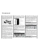
F3A models belong to the category of powered fi xed-
wing model aircraft designed for competition fl ying.
They may be powered by an internal combustion en-
gine or an electric motor. Electric-powered models
are eligible to fl y in the international F3A “pattern”
class, where they are now fully competitive, as well as
in the F5A electric aerobatic class.
On page 158, where the section on fi xed-wing mo-
del programming starts, you will fi nd general notes re-
garding the procedure for installing and setting up the
RC system in a model, and – of course – this also ap-
plies to F3A models, and therefore does not need to
be repeated at this point.
If F3A models are accurately built, they usually ex-
hibit fl ying characteristics which are almost comple-
tely neutral. The perfect aerobatic aircraft has a very
smooth but precise control response, and any move-
ment around any one of its fl ight axes should not af-
fect the other axes.
F3A models are fl own using aileron, elevator and rud-
der controls, and the use of separate servos for each
aileron is almost universal. The fl ying controls are
complemented by control of motor power (throttle
function) and in many cases a retractable undercar-
riage. As a result the servo assignment for channels
1 to 5 is no different from the fi xed-wing models we
have already described.
The auxiliary function “Retracts” is usually assigned
to one of the auxiliary channels 6 to 9. Ideally the re-
tracts are operated using a channel switch without a
centre detent. An optional “extra” – used only if ne-
cessary – is mixture adjustment control for the carbu-
rettor. This is generally controlled by one of the two
INC / DEC buttons on the transmitter, connected to
one of the auxiliary channels otherwise not in use.
When assigning functions to the auxiliary channels at
the transmitter it is advisable to ensure that the cont-
rols required are within easy reach, since the advan-
ced aerobatic pilot has very little time to think about
letting go of the sticks – especially when fl ying in
competition conditions.
Programming
The basic programming of the transmitter has alrea-
dy been described in detail in the section starting on
page 160 … 164, so this section concentrates on tips
specifi c to F3A models.
In the menu …
»Servo adjustment« (page 74)
Servo 1
=>
0% 100% 100% 150% 150%
Servo 2 =>
0% 100% 100%
150% 150%
Servo 3 =>
0% 100% 100%
150% 150%
Servo 4 =>
0% 100% 100%
150% 150%
Rev
SEL
SYM ASY
SYM ASY
cent. – travel
+
– limit +
SEL
… you can adjust the servo travels to suit your model.
It has proved advisable to use at least 100% servo
travel, as precision of control can be perceptibly bet-
ter if relatively large servo throws are employed. This
should be borne in mind when building the model and
designing the control surface linkages. Check the di-
rection of servo rotation, and take care to set the ser-
vo centres accurately at the mechanical level.
Any minor corrections required can be made in the
3rd column of the »
Servo adjustment
« menu during
the fi rst test-fl ights.
The next step is to select the menu …
»Model type« (page 70)
… and activate the idle trim for Channel 1 (normal-
ly “back”; i. e. full-throttle forward). The digital trim now
works at the idle end of stick travel:
SEL
Offset
+100%
2 AIL
Thr. min back
Normal
M O D E L T Y P E
Tail type
Aileron/camber flaps
Brake
Input 1
Motor on C1
The remaining settings can be left as shown in the il-
lustration.
Once you have test-fl own the model and trimmed
it out carefully,
we recommend that you reduce the
trim travel for elevator and ailerons. The model then
responds much more smoothly to any changes you
make at the trim levers, and thereby avoids “over-trim-
ming” the model; with full trim travel a single trim in-
crement can have too powerful an effect: if the model
tends to pull slightly to the left, one click of the trim
causes it to pull right. The increment size of the digital
trims can be altered in the menu …
»Stick mode« (page 76)
… where you simply reduce the number of trim incre-
ments in the “Trim.step” column.
Battery
Free, or aux. function (2nd EL servo)
Free, or aux. function (mixture adjustment)
Free, or aux. function (retracts)
Right aileron
Rudder
Elevator
Aileron or left aileron
Airbrake or throttle or speed controller
(electric model)
Batt
9
8
7
6
5
4
3
2
1
10
Free, or aux. function
Free, or aux. function
Receiv
er
Summary of Contents for mx-24s
Page 1: ...1...
Page 19: ...19 For your notes...
Page 35: ...35 For your notes...
Page 41: ...41 41 For your notes...
Page 57: ...57 For your notes...
Page 63: ...63 63 For your notes...
Page 69: ...69 69 For your notes...
Page 85: ...85 85 For your notes...
Page 99: ...99 For your notes...
Page 143: ...143 For your notes...
Page 191: ...191 For your notes...
Page 212: ...212 212 For your notes...
Page 213: ...213 213 For your notes...
Page 214: ...214 For your notes...
Page 216: ...216...


