37
Fixed-wing models
In the following section you will fi nd the receiver so-
cket sequence which is required for your model, star-
ting with “standard models” with no more than two
control surfaces per wing panel. For a six-fl ap model
please turn to page 38. For an eight-fl ap model you
need a receiver with at least ten servo outputs (twelve
is even better); the receiver socket sequence for this
is described on page 184.
Receiver socket sequence for models with up to
four control surfaces per wing panel
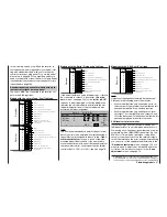
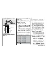
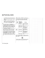
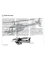
The servos MUST be connected to the receiver out-
puts in the following order:
Models with the “normal” and “V-tail” tail type
Models with the “Delta / Flying wing” tail type
If the model features a second rudder servo, it should
be connected to output 5. A dual mixer (»
Dual mi-
xers
« menu – see page 144) of the “
5
RU
”
type has to be programmed so that the rudder stick
operates the second rudder in parallel with the fi rst
rudder; differential travel of the two rudders is also
possible with this arrangement.
D U A L M I X E R
M i x e r
RU
0%
M i x e r
Diff.
SEL
5
? ?
? ?
0%
SEL
M i x e r
? ?
? ?
0%
SEL
1
2
3
Tips:
The dual mixer shown above permits the pair of rud-
ders or spoilers to be employed as airbrakes using a
transmitter control assigned to input 5 in the »
Trans-
mitter control adjust
« menu, e. g. one of the side-
mounted proportional controls. If you would like to
move the neutral point to one of the two end-points of
the transmitter control, you must set the transmitter
control offset to -100% or +100%; see also page 78.
Models with the “2 EL Sv 3+8” tail type
Second elevator servo
Free, or aux. function, or right fl ap servo
Free, or aux. function or fl ap servo / left fl ap servo
Right aileron servo
Rudder servo
Elevator servo
Aileron servo or left aileron servo
Airbrake or throttle or speed controller
(electric model)
Batt
9
8
7
6
5
4
3
2
1
Free, or aux. function
Battery
Receiv
er
Note:
Outputs not required should simply be left unused.
Please note the following points in particular:
• If your model features only one aileron servo, re-
ceiver output 5 (right aileron) should either be left
unused or employed for an auxiliary function.
• If your model features only one fl ap servo, recei-
ver output 7 (for the right fl ap) and outputs 9 and
10 for the inboard pair of fl aps should either be left
unused or employed for auxiliary functions.
PPM receivers of other makes
If you are using a PPM-FM receiver made by ano-
ther manufacturer* in a model which was previously
fl own using a non-Graupner transmitter, and you wish
to operate it with a
GRAUPNER
transmitter, e. g. the
mx
-24s for Trainer mode operations, it may be ne-
cessary to re-connect servos to the receiver outputs
in the order stated on the previous page. Alternatively
you can carry out the appropriate adjustments in the
»
Receiver output swap
« menu, see page 153. You
may also need to adjust servo travels and directions
of rotation; this is always carried out in the »
Servo
adjustment
« menu; see page 74.
Free, or aux. function
Free, or aux. function, or right fl ap servo
Free, or aux. function or fl ap servo / left fl ap servo
Right aileron servo
Right V-tail servo
Left V-tail servo
Aileron servo or left aileron servo
Airbrake or throttle or speed controller
(electric model)
Batt
9
8
7
6
5
4
3
2
1
Free, or aux. function
Battery
Receiv
er
Free, or aux. function
Free, or aux. function, or right fl ap servo
Free, or aux. function or fl ap servo / left fl ap servo
Free, or aux. function (right rudder)
Rudder
Right elevon servo
Left elevon servo
Airbrake or throttle or speed controller
(electric model)
Batt
9
8
7
6
5
4
3
2
1
Free, or aux. function
Battery
Receiv
er
Battery
Free, or aux. function
Free, or aux. function, or right fl ap servo
Free, or aux. function or fl ap servo / left fl ap servo
Right aileron servo
Rudder servo
Elevator servo
Aileron servo or left aileron servo
Airbrake or throttle or speed controller
(electric model)
Batt
9
8
7
6
5
4
3
2
1
Free, or aux. function
Receiv
er
* GRAUPNER does not guarantee that GRAUPNER radio cont-
rol systems will work correctly in conjunction with receiving sys-
tems and radio control equipment made by other manufacturers.
Summary of Contents for mx-24s
Page 1: ...1...
Page 19: ...19 For your notes...
Page 35: ...35 For your notes...
Page 41: ...41 41 For your notes...
Page 57: ...57 For your notes...
Page 63: ...63 63 For your notes...
Page 69: ...69 69 For your notes...
Page 85: ...85 85 For your notes...
Page 99: ...99 For your notes...
Page 143: ...143 For your notes...
Page 191: ...191 For your notes...
Page 212: ...212 212 For your notes...
Page 213: ...213 213 For your notes...
Page 214: ...214 For your notes...
Page 216: ...216...

