144
Program description:
Mixers
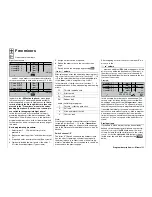
D U A L M I X E R
Mixer
0%
Diff.
SEL
? ?
? ?
0%
SEL
? ?
? ?
0%
SEL
? ?
? ?
Mixer
Mixer
1
2
3
The four dual mixers are designed for coupling two
channels together to provide same-sense “
”
and
opposite-sense “
” mixing, as required for a V-
tail, for example. However, these mixers can be used
with any channels, with the option of differential travel
for the opposed function.
In software terms this type of “dual mixer” is imple-
mented as standard for fl aperons as well as V-tail,
with the two aileron servos connected to receiver out-
puts 2 + 5, and the two pairs of fl ap servos to outputs
6 + 7 and 9 + 10. Flaperons are controlled by the ai-
leron stick and the transmitter control which is assig-
ned to input “6” in the »
Transmitter control adjust
«
menu. Any further “…
2” mixer which you set up
then operates the two ailerons as ailerons, while a “…
5” mixer operates them as fl aps, i. e. moves them
in the same direction. Similarly, a free mixer “…
6”
operates both fl aps as fl aps, while a “…
7” mixer
operates them as ailerons; see page 137.
The four dual mixers in this menu can also be used
to couple together two other receiver outputs in the
same way; a process which would normally require
more complex programming involving free mixers.
At this point we will give an example of this type of
programming (see also the examples on pages 173
and 184):
Large scale gliders often feature six wing control sur-
faces – sometimes even eight – rather than four, all
of which are required to have superimposed aileron /
fl ap functions. In our example the two additional wing
fl aps are connected to receiver outputs 11 and 12.
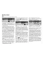
Start by selecting one of the dual mixers with the ro-
Dual mixer
Same-sense / opposite-sense coupling of two channels
tary control pressed in. After a brief press on the rota-
ry control in the left-hand
SEL
fi eld, enter Output “11”
in the highlighted
??
fi eld using the rotary cont-
rol, and enter Output “12” in the same way, using the
middle
SEL
fi eld:
12
0%
Diff.
SEL
SEL
11
? ?
? ?
0%
SEL
? ?
? ?
0%
D U A L M I X E R
Mixer
Mixer
Mixer
1
2
3
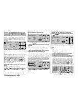
Note:
The symbols “
” and “
” indicate that the
corresponding inputs act upon the servos coupled
by the mixer in the same and opposed directions re-
spectively – they do not indicate the direction of ser-
vo rotation! If the second control surface moves in the
wrong “sense” (direction), simply interchange the two
inputs, or use the servo reverse facility in the »
Servo
adjustment
« menu; see page 74.
In the right-hand column you should now defi ne the
“degree of differential”, using the method described in
the »
Wing mixers
« menu (see page 110). The effect
of this function is to reduce the travel of the down-go-
ing wing fl ap compared with the full travel of the fl ap
on the opposite wing when an aileron command is gi-
ven. This process generates exactly the dual coupling
for servos 11 + 12 which is required for this arrange-
ment.
(Pressing
CLEAR
erases the dual mixer, and / or re-
sets the degree of differential to 0%.)
The two additional servos should now “follow” servos
2 + 5 as ailerons when an aileron command is given,
and should follow servos 6 + 7 as fl aps when a fl ap
command is given. To operate this combination cont-
rol system all you require is two more free mixers: Li-
nearMIX 1 links the aileron stick to the two servos 11
and 12, and LinearMIX 2 links input 7 to them.
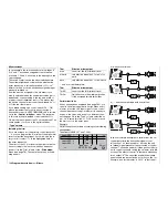
Move to the »
Free mixers
« menu, defi ne two mixers
which are not yet in use, e. g. linear mixers 1 + 2, and
set them up in the following manner:
Tr
6
??
??
- - - -
??
??
- - - -
SEL SEL
AI
12
7
11
SEL
=>
=>
LinearMIX
type
1
LinearMIX
LinearMIX
LinearMIX
2
3
4
from
to
Adjust
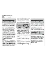
(The mixer “AIL
12” moves these two servos in op-
posite directions “
”, i. e. as ailerons, while the
mixer “7
11” moves them in the same direction
“
”.)
The mixer settings can now be defi ned on the second
display page. If you wish, you can assign a switch to
the mixer, as shown in this example.
We need to be able to operate the two additional con-
trol surfaces as fl aps (as well as ailerons), and this
is effected by assigning the same transmitter cont-
rol to the fl ight phase specifi c input 8 in the »
Trans-
mitter control adjust
« menu as to input 6 (note that
“Input 7” is automatically de-coupled from “servo 7” if
you select “2 AIL 2/4 FL” in the “Ailerons / fl aps” line
of the »
Model type
« menu). We recommend that you
assign one of the two IN / DEC buttons 5 or 6 as the
transmitter control for both inputs, as their positions
are stored separately for each fl ight phase – unlike
the side-mounted proportional controls.
If you want the fl ap control system to be different in
each fl ight phase, you will need to adjust the offset
value and possibly also the travel in the »
Transmitter
control adjust
« menu. However, the degree of diffe-
rential can only be set to one value, since the “Dual
mixers” cannot be programmed separately for diffe-
rent fl ight phases.
Summary of Contents for mx-24s
Page 1: ...1...
Page 19: ...19 For your notes...
Page 35: ...35 For your notes...
Page 41: ...41 41 For your notes...
Page 57: ...57 For your notes...
Page 63: ...63 63 For your notes...
Page 69: ...69 69 For your notes...
Page 85: ...85 85 For your notes...
Page 99: ...99 For your notes...
Page 143: ...143 For your notes...
Page 191: ...191 For your notes...
Page 212: ...212 212 For your notes...
Page 213: ...213 213 For your notes...
Page 214: ...214 For your notes...
Page 216: ...216...


