138
Program description:
Mixers
Mixer ratios and mixer neutral point
Now that we have explained the wide-ranging nature
of the mixer functions, the following section describes
how to program linear and non-linear mixer curves.
For each of the twelve available mixers the mixer cur-
ves are programmed on a second page of the screen
display. Hold the rotary control pressed in, and se-
lect the line for the mixer you wish to adjust, then se-
lect the arrow button “
” using the rotary control. A
brief press on the rotary control or the
ENTER
button
takes you to the graphic page.
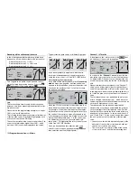
Linear mixers 1 ... 8: setting linear curves
As an example with a practical application we will de-
fi ne a linear mixer curve in the following section desi-
gned to solve the following problem:
We have a powered model with two fl ap servos con-
nected to receiver outputs 6 and 7, which were pro-
grammed in the »
Model type
« menu. The fl aps are to
be employed as landing fl aps, i. e. when the associa-
ted transmitter control is operated they defl ect down
only. However, this fl ap movement requires an eleva-
tor trim correction to counteract an unwanted pitch
trim change.
In the »
Transmitter control adjust
« menu, assign an
unused side-mounted proportional control, e. g. con-
trol 9, to input 6. We choose this input because the
transmitter control assigned to input 6 by default con-
trols the two servos connected to receiver outputs 6
and 7, operating as simple wing fl aps, as you can see
from the table on the opposite page.
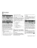
»
Transmitter control adjust
« menu:
0%
+
100%+100% 0.0 0.0
Cnt. 9
0% +100%+100% 0.0 0.0
free
0% +100%+100% 0.0 0.0
0% +100%+100% 0.0 0.0
SYM ASY
ASY
SYM
SEL
SEL
«normal »
Input 5
Input 6
Input 7
Input 8
–
–time+
offset
free
free
Note:
If you select two fl aps (“2 FL”) in the »
Model type
«
menu, input 7 is automatically blocked to avoid pos-
sible malfunctions. However, in the interests of safe-
ty we strongly recommend that you make it a matter
of course to leave or reset all inputs not currently re-
quired to “free”.
Start by moving this transmitter control to the forward
end-point, and adjust the landing fl ap linkages so that
they are in the neutral (closed) position at this setting.
If you move the control back, the fl aps should move
down; if not, you must reverse the direction of servo
rotation.
Now we turn our attention to the fi rst mixer in the
screen-shot shown on page 135, which is “6
EL”;
this is designed to provide elevator trim. Switch 4 has
been assigned to this mixer:
SEL
EL
6
=>
=>
C1
8
S
EL
10
EL
Tr
4
G4
7
off
off
=>
=>
SEL
SEL
SEL
LinearMIX
type
1
LinearMIX
LinearMIX
LinearMIX
2
3
4
from
to
Adjust
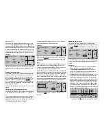
Use the rotary control to move to the arrow
in the
bottom line. A brief press on the rotary control now
switches to the second screen page:
Linear MIX 1
off
6
EL
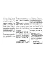
If this display appears, you have not activated the mi-
xer by operating the assigned switch – in this case
“4”.
To correct this, operate the switch:
Linear MIX 1
Mix input
0%
m
OU
T
P
U
T
--
+
10
0
STO
ASY
SYM
CLR
6
EL
0%
0%
O f f s e t
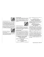
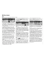
The solid vertical line in the graph represents the cur-
rent position of the transmitter control assigned to in-
put 6. The solid horizontal line shows the mixer ratio,
which currently has the value of zero over the who-
le stick travel; this means that the elevator will not “fol-
low” when the fl aps are operated.
The fi rst step is to defi ne the
offset
(mixer neutral
point):
The dotted vertical line indicates the position of the
mixer neutral point (“offset”), i. e. that point along the
control travel at which the mixer has no infl uence on
the channel connected to its output. As standard this
point is set to the centre position.
In our example the neutral position of the fl aps is lo-
cated at the forward end-point of the side-mounted
proportional control, so we must also shift the mixer
neutral point exactly to that point, as no elevator cor-
rection is required at that setting. Move control 9 in
the direction of +100%, select
STO
using the rotary
control and press the rotary control briefl y. The dotted
vertical line now moves to this point – the new mixer
neutral point – which always retains the “OUTPUT”
value of zero in accordance with the mixer defi nition.
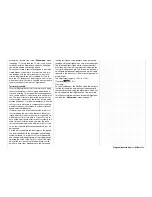
As it happens, this setting is diffi cult to show in a
screen-shot, so,
in the interests of clarity
, we will
change the “offset” value to only +75%.
0%
0%
+ 7 5 %
m
OU
T
P
U
T
--
+
100
STO
ASY
SYM
CLR
6
Linear MIX 1
Mix input
EL
O f f s e t
Summary of Contents for mx-24s
Page 1: ...1...
Page 19: ...19 For your notes...
Page 35: ...35 For your notes...
Page 41: ...41 41 For your notes...
Page 57: ...57 For your notes...
Page 63: ...63 63 For your notes...
Page 69: ...69 69 For your notes...
Page 85: ...85 85 For your notes...
Page 99: ...99 For your notes...
Page 143: ...143 For your notes...
Page 191: ...191 For your notes...
Page 212: ...212 212 For your notes...
Page 213: ...213 213 For your notes...
Page 214: ...214 For your notes...
Page 216: ...216...

