53
53
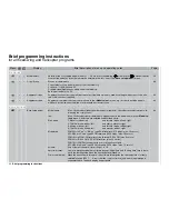
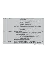
Brief programming instructions
Note / Recommendation:
If you program the offset value in »
Model type
« to about 90%, then the remainder of
the transmitter control travel between the selected offset and full travel has no effect.
Crow:
positions the control surface pairs AILE, FLAP and FL2 for the desired braking effect
(generally AILE up and FLAP, FL2 down).
Diff. reduct.:
reduces the differential set in the multi-fl ap menu according to the airbrake defl ection.
Mechanical differential can also be eliminated if the entered Diff. red. value is greater
than the Diff. value set in the multi-fl ap menu.
Elevat. curve: eight-point mixer designed to compensate for pitch trim changes when the brake func-
tion is operated.
Aileron 2
4 rudder:
switchable mixer which causes the rudder to follow the aileron movement to a variable
extent.
Elevator 3
6 fl aps:
appears only if you select “1 AIL 1 FL” in the “Aileron / camber fl aps” line of the »
Model
type
« menu. This linear mixer defi nes the effect of the fl aps on the elevator; the setting
is usually asymmetrical.
Flaps 6
3 elevator:
switchable mixer which causes the elevator to follow the fl ap movement to a variable ex-
tent; the setting is usually asymmetrical.
•
Helicopter mixer
Flight phase specifi c programming
a)
eight-point curves for “collective pitch”, “channel 1
throttle” and “channel 1
tail rotor”; set as in the
“Channel 1 curve” menu; and
b)
linear mixer inputs (0 … 100%) for the mixers “tail rotor
throttle”, “roll
throttle”, “roll
tail rotor”,
“pitch-axis
throttle” and “pitch-axis
tail rotor”.
Gyro suppression:
fl ight phase specifi c suppression of gyro effect when a tail rotor command is given (0
… 199%), varying with the position of the tail rotor stick. The effect of values above
100% is to provide total suppression before full defl ection of the tail rotor.
Swashplate rotation: (virtual) rotation of the swashplate in both directions (-90° … +90°).
Swashplate limiter:
travel limit, applies only when pitch-axis and roll commands are applied simultaneous-
ly (adjustment range 100 … 149% and “off”).
In the auto-rotation phase the following adjustments are available:
eight-point collective pitch curve and throttle position AR (-125% … +125%), tail rotor AR (-125% … +125%),
plus gyro suppression and swashplate rotation.
122
•
•
Free mixers
Linear mixers 1 … 8 or curve mixers 9 … 12 are selected with the rotary control pressed in.
The mixer input (any control function) “from” and the output “to” are determined in the “from / to” column using the
associated
SEL
function and the rotary control. If a constant control function is required as input, e. g. motor ON /
OFF, then select the letter “S” in the “from” column, and assign a mixer switch in column 4. Note: without an assig-
135
Display
Menu
Brief description of menu and operating notes
Page
Summary of Contents for mx-24s
Page 1: ...1...
Page 19: ...19 For your notes...
Page 35: ...35 For your notes...
Page 41: ...41 41 For your notes...
Page 57: ...57 For your notes...
Page 63: ...63 63 For your notes...
Page 69: ...69 69 For your notes...
Page 85: ...85 85 For your notes...
Page 99: ...99 For your notes...
Page 143: ...143 For your notes...
Page 191: ...191 For your notes...
Page 212: ...212 212 For your notes...
Page 213: ...213 213 For your notes...
Page 214: ...214 For your notes...
Page 216: ...216...

