112
Program description:
Mixers
suppress the down-aileron defl ection completely, i. e.
only the up-going aileron moves at all, and this arran-
gement is sometimes called the “split” setting. Split ai-
lerons not only tend to suppress adverse yaw, but can
even generate positive yaw, which means that the
model yaws slightly in the direction of the turn when
an aileron command is given. In the case of large mo-
del gliders smooth turns can then be fl own using ai-
lerons alone, which is usually by no means the case
with other arrangements.
The adjustment range of -100% to +100% makes it
possible to set the correct direction of differential re-
gardless of the direction of rotation of the aileron ser-
vos. “0%” corresponds to a normal linkage, i. e. no dif-
ferential, while “-100%” or “+100%” represents the
“split” function.
For aerobatic fl ying low absolute values are required,
to ensure that the model rotates exactly along its lon-
gitudinal axis when an aileron command is given. Mo-
derate values around -50% or +50% are typical for
making thermal turns easier to fl y. The split setting
(-100%, +100%) is popular with slope fl yers, where
ailerons alone are often used for turning the model.
Note:
Although negative values can be programmed to re-
verse the direction of servo rotation, this is not usually
necessary if the correct channels are used.
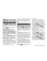
Camber-changing fl ap differential
In the “
AI
” line of the multi-fl ap menu (see below)
you can set the extent to which the fl aps follow the ai-
lerons when an aileron command is given; this is en-
tered as a percentage value. For this reason fl ap dif-
ferential has the same effect as aileron differential,
i. e. it reduces the travel of the down-going fl ap when
an aileron command is given.
The adjustment range of -100% to +100% makes it
possible to set the correct direction of differential. A
“0%” value corresponds to a normal linkage, i. e. the
servo travel is the same up and down. A setting of
“-100%” or “+100%” means that the down-travel of the
fl aps is reduced to zero when an aileron command is
given, i. e. it creates the “split” set-up.
Note:
Negative values are not usually necessary if the cor-
rect channels are used.
Model type: “1 AIL”
If you enter “1 AIL” in the “Ailerons / fl aps” line of the
»
Model type
« menu (see page 70), the transmitter’s
“Wing mixer menu” will look similar to the screen-shot
below:
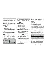
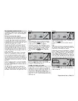
Brake settings
Aileron
=>
2–>4 rudder
0%
W I N G M I X E R S
A brief press on the rotary control from the fi rst line of
this page takes you to the following sub-menu …
Brake settings
Note:
The “Brake settings” menu is switched “off” if you en-
tered “Motor on C1 forward / back” in the »
Model
type
« menu (see page 70), and leave “yes” for the
currently active fl ight phase in the “Motor” column of
the »
Phase settings
« menu (see page 100). You may
therefore need to switch fl ight phases:
B R A K E S E T T I N G S
Elevat. curve
=>
Since it is impossible to set up a butterfl y (crow) sys-
tem or aileron differential if your model is only fi tted
with a single aileron servo, this menu offers no further
set-up options apart from a “pointer” to the “Elevat.
curve” sub-menu. For this reason we give the rotary
control a brief press and immediately move on:
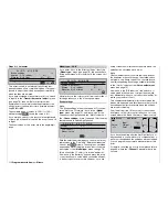
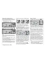
Brake
Input
+50%
Output
0%
off
m
OU
T
P
U
T
--
+
10
0
Elevator
Point
?
Curve
If you have the feeling that you will need to set pitch
trim compensation when the airbrakes are extended,
you can program an automatic elevator mixer at this
point.
For details on setting up a curve mixer please refer to
page 90, where the »
Channel 1 curve
« mixer is dis-
cussed.
Aileron 2
4 rudder
SEL
Brake settings
Aileron
=>
2–>4 rudder
0%
W I N G M I X E R S
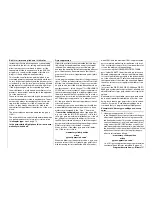
This mixer causes the rudder to “follow” automatically
when an aileron command is given.
Select the
SEL
fi eld, and give the rotary control a
brief press. You can now set the desired value for this
function using the rotary control. The mixer direction
must be chosen to ensure that the rudder moves in
the same direction as the up-going aileron.
If you assign a switch to this function in the right-hand
column, you will be able to switch the mixer on and off
in fl ight.
The available range of values is -150% to +150%,
Summary of Contents for mx-24s
Page 1: ...1...
Page 19: ...19 For your notes...
Page 35: ...35 For your notes...
Page 41: ...41 41 For your notes...
Page 57: ...57 For your notes...
Page 63: ...63 63 For your notes...
Page 69: ...69 69 For your notes...
Page 85: ...85 85 For your notes...
Page 99: ...99 For your notes...
Page 143: ...143 For your notes...
Page 191: ...191 For your notes...
Page 212: ...212 212 For your notes...
Page 213: ...213 213 For your notes...
Page 214: ...214 For your notes...
Page 216: ...216...

