21
1
2
3
4
5
6
Description of transmitter
Note:
If you intend to work on the interior of the trans-
mitter, remember not to switch the transmitter on.
Disconnect the transmitter battery from the po-
wer socket. Take great care not to touch soldered
joints with any metallic object.
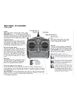
Back panel
Opening the transmitter case
Undo the six recessed screws in the rear face of
the transmitter using a cross-point screwdriver (size
PH1). Be sure to read the section on page 16 before
you proceed!
Synthesizer RF and Scan Module
The frequency band can be changed quickly and ea-
sily by carefully withdrawing the RF module using the
two side-mounted lugs. Note: plug-in crystals are not
necessary due to the PLL Synthesizer technology
employed in the transmitter.
The channel is selected under software control imme-
diately after you switch the transmitter on; see page
25. The new form of DUAL-CONVERSION scanning
receiver is an integral part of the RF module. This en-
ables you to check which channels in the vicinity of
the transmitter are already in use; see page 24.
When you re-install the module, ensure that the con-
tact pins are not bent.
Charge socket
Please read the notes on battery charging
on pages 12 … 13.
Polarity:
Diagnosis socket (DSC*)
A special lead is available under Order No.
4178.1
which connects the
mx
-24s transmitter directly to
a suitable receiver. If the transmitter is switched off,
plugging the lead in automatically switches it on. At
the same time the RF module remains disabled, with
the result that no signal is transmitted via the aerial.
The DSC socket can also be used as a Teacher or
Pupil socket in a Trainer system; for more details ple-
ase refer to page 18 and the description of the »
Tea-
cher / pupil
« menu on page 150.
Teacher / PC module,
Order No.
3290.22
An optional module is available which converts the
mx
-24s transmitter into an opto-electronic Teacher
unit for use in a Trainer system. For Trainer mode ope-
rations you will also need to connect a light-pipe (opti-
cal cable) to the appropriate socket on the transmitter;
this is available as an optional accessory. The second
socket on the module is for data transfer between two
mx
-24s transmitters, or between an
mx
-24s and a
PC. The accessories required for this are also listed in
the Appendix.
Battery compartment
If you need to remove the battery, press on the two
corrugated areas with both thumbs, then slide the
battery compartment cover in the direction of the ar-
row.
* DSC = Direct Servo Control
SYNTHESIZER transmitter RF mo-
SYNTHESIZER transmitter RF mo-
dules for the
dules for the
mx
mx
-24s transmitter
-24s transmitter
Order No.
Order No.
3853.35
3853.35
35 MHz band
35 MHz band
Order No.
Order No.
3853.40
3853.40
40/41 MHz band
40/41 MHz band
Summary of Contents for mx-24s
Page 1: ...1...
Page 19: ...19 For your notes...
Page 35: ...35 For your notes...
Page 41: ...41 41 For your notes...
Page 57: ...57 For your notes...
Page 63: ...63 63 For your notes...
Page 69: ...69 69 For your notes...
Page 85: ...85 85 For your notes...
Page 99: ...99 For your notes...
Page 143: ...143 For your notes...
Page 191: ...191 For your notes...
Page 212: ...212 212 For your notes...
Page 213: ...213 213 For your notes...
Page 214: ...214 For your notes...
Page 216: ...216...


