54
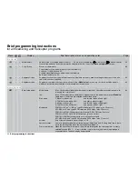
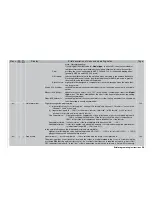
Brief programming instructions
Brief programming instructions
for all fi xed-wing and helicopter programs
ned switch this type of mixer delivers a constant signal only.
Preceding mixers (“
” symbol) and / or the trim (“Tr” of sticks 1 … 4) are included when the mixer input is set in
the “Type” column. Search for appropriate symbol “
”, “Tr” or “Tr
” using the rotary control. Optionally all mixers
can be assigned a switch.
Setting of mixer inputs and directions for linear mixers:
Change screen page in the “Setting” column with a brief press on the rotary control. Select
ASY
or
SYM
and set
desired mixer input between 0 and +/-150% using the rotary control. For asymmetrical setting, select page using
the input transmitter control (vertical line in the graph) and for switched channel “S” with associated switch.
Setting of non-linear mixer curves for curve mixers 9 … 12:
Between the two end-points “L” (Low) and “H” (High) up to six additional curve points can be defi ned. Basic notes
on operation can be found in the description of the »
Channel 1 curve
« menu on pages 90 / 92.
Shifting the offset point (mixer neutral point):
Use the transmitter control to move the bar in the graph to the desired position, select
STO
and press the rotary
control briefl y. The offset point is returned to the centre position using the bottom
CLR
function.
Notes:
DUAL RATE may limit the movement range of the vertical line. Mixers may also have been suppressed in the
»
MIX active in phase
« menu.
•
•
MIX active/phase
The mixers 1 … 12 can be disabled separately for each fl ight phase. In the »
Free mixers
« menu they are then
suppressed separately for each fl ight phase.
142
•
•
MIX-only channel
This function is used to separate the link between transmitter controls 1 … 12 and the associated servo, i. e. the
transmitter control only continues to affect the relevant channel as a mixer input. In this case the de-coupled servo
is only accessible via mixers.
142
•
•
Dual mixer
Four mixers designed for coupling two channels in such a way that they work in the same and opposed directions.
Example: differential rudder travel on a V-tail. In this case “
EL
” is defi ned as the “same-direction” function,
and “
RU
” as the “opposite” function. In this case it is essential to enter “normal” under Tail type in the »
Model
type
« menu!
144
•
Swashplate mixer
Mixer inputs for collective pitch, roll and pitch-axis can be set individually (-100% … +100%), except for helicop-
ters with one servo for collective pitch control.
CLEAR
resets altered values to the default of +61%.
Note:
Ensure that servos are not mechanically obstructed or stalled if you set large values at this point.
145
Special functions
Special functions
•
•
Fail-safe adjust
In PCM20 mode:
“Time”:
all servos to “hold” mode, or enter a delay time (1, 0.5 or 0.25 sec.) using the rotary control, after
146
Display
Menu
Brief description of menu and operating notes
Page
Summary of Contents for mx-24s
Page 1: ...1...
Page 19: ...19 For your notes...
Page 35: ...35 For your notes...
Page 41: ...41 41 For your notes...
Page 57: ...57 For your notes...
Page 63: ...63 63 For your notes...
Page 69: ...69 69 For your notes...
Page 85: ...85 85 For your notes...
Page 99: ...99 For your notes...
Page 143: ...143 For your notes...
Page 191: ...191 For your notes...
Page 212: ...212 212 For your notes...
Page 213: ...213 213 For your notes...
Page 214: ...214 For your notes...
Page 216: ...216...

