39
39
Fixed-wing models
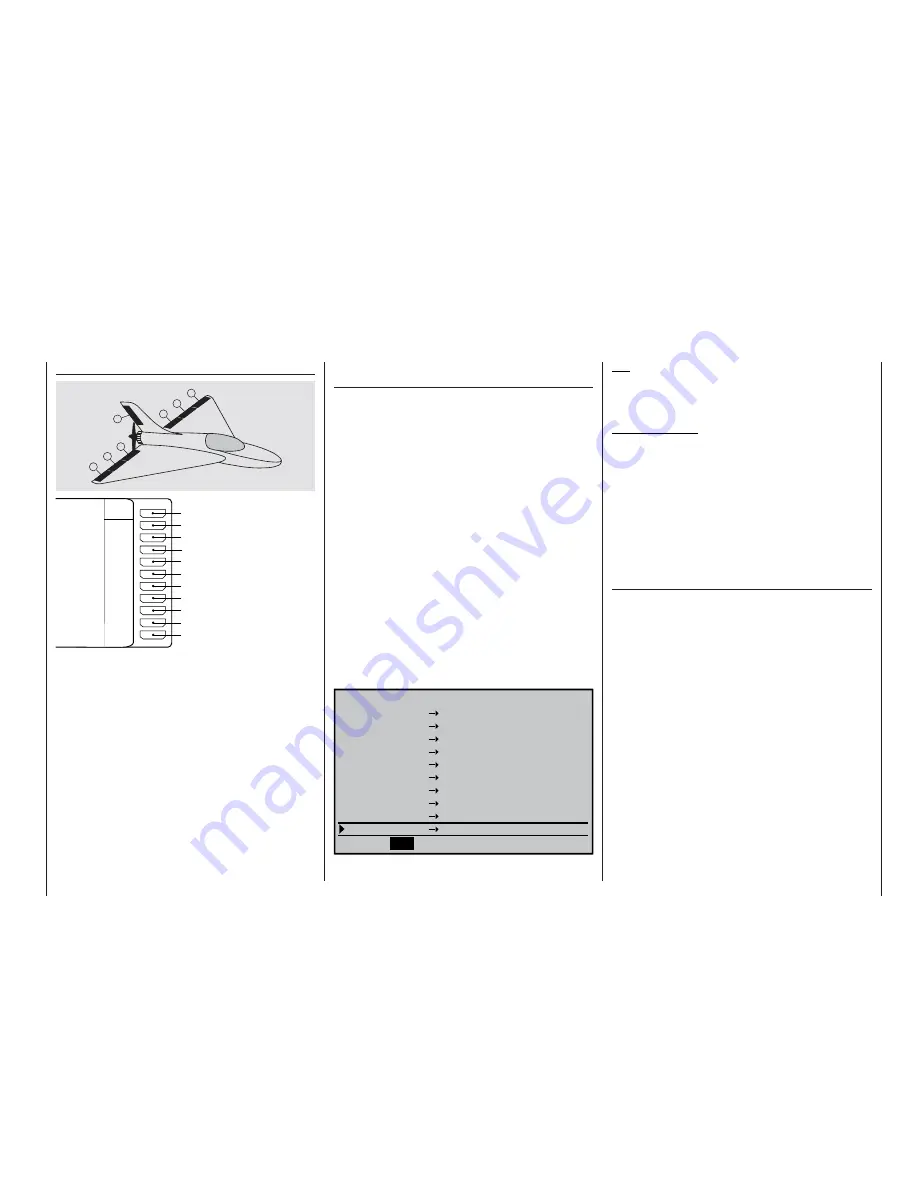
Models with the “Delta / Flying wing” tail type
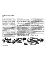
Deltas / fl ying wings with two rudders
See set-up notes on the preceding double page,
right-hand side.
left
right
8
7
3
2
6
1
4
Battery
Right fl ap 2
Right fl ap
Left fl ap
Free, or right rudder, or aux. function
Rudder or left rudder
Right elevon
Left elevon
Left fl ap 2
Batt
9
8
7
6
5
4
3
2
1
10
Free, or aux. function or throttle
Free, or aux. function
Receiv
er
Interchanging receiver outputs with PCM20 and
SPCM20 receivers
The receiver assignment stated below should be
used for both tail types in order to avoid servos 9 and
10 running jerkily. Carry out the following steps in the
»
Receiver output swap
« menu:
• assign servo 9 to output 1, and,
• assign servo 10 to output 8.
Moreover, if you …
• … assign servo 1 to output 9, then receiver output
9 is available for other purposes, perhaps for air-
brakes, or for throttle using the throttle / airbrake
stick, and
• … assign servo 8 to output 10, then a servo con-
nected to output 10, if present, can be operated by
a transmitter control assigned to input 8 (»
Trans-
mitter control adjust
« menu), typically for cont-
rolling an auxiliary function.
Servos connected to these two outputs (9 + 10) do
run smoothly provided that they are not affected by
mixers.
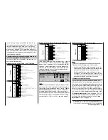
The »
Receiver output swap
« menu (page 153)
should therefore be programmed as follows:
R e c e i v e r O u t p u t
Servo
10
8
10
SEL
9
Output
1
Servo
Servo
Servo
Servo
Servo
Servo
Servo
Servo
Servo
2
3
4
5
6
7
1
8
9
7
6
5
4
3
2
Output
Output
Output
Output
Output
Output
Output
Output
Output
PCM20, SPCM20
Tip:
You should also select this “PCM sequence” for a six-
fl ap wing if you are using a PPM receiver with only
eight or nine servo sockets.
Important notes:
• If you re-assign the receiver outputs, please note
that any subsequent changes, such as servo tra-
vel adjustment, Dual Rates / Expo, mixers etc.,
must still refer to the basic receiver sequence.
• If you swap over the receiver outputs, please note
that the Fail-Safe programming (“hold” or “pos.”) in
SPCM20 and APCM24 mode always relates to the
default receiver socket numbers; in PCM20 mode,
battery fail-safe always affects receiver output 1.
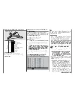
How are the pairs of ailerons and fl aps cont-
rolled?
1. Both pairs of fl aps are controlled with the aile-
ron function using the aileron stick
• By default, the aileron stick only controls the
two aileron servos 2 + 5. Values other than
zero for the fl aps FL and (if present) FL2 can
be entered individually in the “Multi-fl ap menu”
of the »
Wing mixers
« menu.
2. The ailerons are controlled by the fl ap function
using input 6 (e. g. using the INC / DEC buttons
CTRL 5 or 6)
• By default, a transmitter control which is as-
signed to “Input 6” in the »
Control adjust
«
menu controls the flaps and (if present) FL2
with 100% travel. Values other than zero for
the ailerons, and – if wished – reduced travels
for the flaps, can be entered individually in the
“Multi-flap menu” of the »
Wing mixers
« menu.
• If you choose “2 AIL 2 FL” in the “Ailerons /
fl aps” line of the »
Model type
« menu, a trans-
mitter control assigned to “Input 7” is de-cou-
pled in the software in order to avoid control er-
Summary of Contents for mx-24s
Page 1: ...1...
Page 19: ...19 For your notes...
Page 35: ...35 For your notes...
Page 41: ...41 41 For your notes...
Page 57: ...57 For your notes...
Page 63: ...63 63 For your notes...
Page 69: ...69 69 For your notes...
Page 85: ...85 85 For your notes...
Page 99: ...99 For your notes...
Page 143: ...143 For your notes...
Page 191: ...191 For your notes...
Page 212: ...212 212 For your notes...
Page 213: ...213 213 For your notes...
Page 214: ...214 For your notes...
Page 216: ...216...


