34
Digital trims
Description of function, and C1 cut-off trim
Digital trims with visual and audible indicators
Both the dual-axis stick units are fi tted with digital trim
systems. When you give the trim lever a brief push
(one “click”), the neutral position of the associated
stick channel changes by one increment. If you hold
the trim lever in one direction, the trim value changes
continuously in the corresponding direction with incre-
asing speed. The trim increment can be set to any va-
lue in the range “1” to “10” in the »
Stick mode
« menu
(see pages 76 / 77), corresponding to servo travel of
around 0.2% … 3% per click. The current position and
numerical trim value are displayed on the screen.
The degree of trim offset is also “audible”, as the pitch
of the tone changes to refl ect the setting. When you
are fl ying a model, you can fi nd the trim centre posi-
tion easily without having to look at the screen: if you
over-run the centre setting, the trim stays in the cen-
tre position for a moment before continuing.
The current trim values are automatically stored when
you switch from one model memory to another.
The digital trims can also be stored globally or se-
parately for each fl ight phase within a model memo-
ry, with the exception of the “C1” (Channel 1) trim,
which is the throttle / airbrake trim on a fi xed-wing
model. The “global” or “phase” setting is selected in
the »
Stick mode
« menu (see pages 76 / 77). Note
that the C1 trim is always set to “global” in the softwa-
re, i. e. it acts independently of any fl ight phases you
may have set.
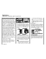
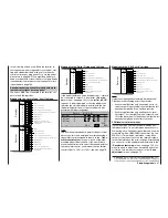
In the basic display this pre-set is indicated by a form
of “shadow” at the trim display bars:
• Shadow present
= global,
• Shadow suppressed = fl ight phase specifi c.
In the model memory to which the following screen-
shot relates two trims have been set separately for
each fl ight phase (“phase” setting):
Model name
#01 0:05h SPCM20
H-J.Sandbrunner
10.9V
0:10h C65
0 0 0
0
Stop watch
Flight tim
0 00
0 00
:
:
1. Fixed-wing model aircraft
The C1 trim features a special function which
makes it easy to re-locate the correct idle setting
of an internal-combustion engine – provided that
you have selected “Throttle min. forward or back”
in the “Motor” line of the »
Model type
« menu (see
page 70). If not, the cut-off trim is permanently
disabled.
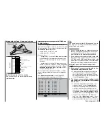
Initially you use the trim lever in the usual way to
select a reliable idle setting for the motor. If you
move the C1 trim lever to its end-point in the direc-
tion of “motor cut-off”, pushing the lever in a single
movement, a marker appears on the screen at the
last position. You can now return to the correct idle
setting for starting the motor simply by pushing the
trim one click in the direction of “open throttle”.
Notes:
•
Since this trim function only takes effect in the
“Motor stopped” direction, the screen image
shown above changes if you alter the thrott-
le minimum position of the C1 stick from “back”
(as shown in the screen-shot above) to “for-
ward” in the “Motor” line of the »
Model type
«
menu.
•
Naturally you can assign the C1 stick to the
left-hand dual-axis stick unit if you prefer; see
the »
Base setup model
« menu, described on
page 64.
2.
Model helicopters
In Helicopter mode the C1 trim has another fea-
ture in addition to “cut-off trim”, as described under
“Fixed-wing model aircraft” above; this time in con-
junction with the “Throttle limit function”: using a
“throttle limit slider” the throttle servo travel can be
limited in the direction of full throttle. For more de-
tails of this please turn to page 82.
Note regarding helicopters:
The C1 trim only affects the throttle servo and not
the collective pitch servos; it also works only in the
direction of idle. Please note that the helicopter
throttle servo must be connected to receiver out-
put 6 (see Receiver socket assignment on page
43).
Digital trims
0:30h SPCM20
ndbrunner
0:30h V65
28100
0
Stop
Flight
0 00
0 00
:
:
om Modèle
Current
trim position
Trim value
Trim
direction indicator
C1 trim lever
Last C1 trim position
Idle direction
CM20
r
K65
28100
0
Stop w
Flight
0 00
0 00
:
:
le
Marker indicates the last C1
trim position (idle setting)
Throttle limit slider
Trim position at which the motor is cut
Summary of Contents for mx-24s
Page 1: ...1...
Page 19: ...19 For your notes...
Page 35: ...35 For your notes...
Page 41: ...41 41 For your notes...
Page 57: ...57 For your notes...
Page 63: ...63 63 For your notes...
Page 69: ...69 69 For your notes...
Page 85: ...85 85 For your notes...
Page 99: ...99 For your notes...
Page 143: ...143 For your notes...
Page 191: ...191 For your notes...
Page 212: ...212 212 For your notes...
Page 213: ...213 213 For your notes...
Page 214: ...214 For your notes...
Page 216: ...216...

