81
Program description:
Transmitter controls
Column 3 “offset”
The centre point of each transmitter control, i. e. its
zero point, can be changed in this column; the adjust-
ment range is -125% to +125%.
Pressing
CLEAR
resets the offset value to 0%.
Column 4 “-”
In this column you set the control travel within the ran-
ge -125% to +125%. At the same time you can use
the software to reverse the direction of effect of the
transmitter control. In contrast to altering servo travel,
changing the transmitter travel setting affects all mi-
xer and coupling inputs, i. e. all servos which are infl u-
enced by the transmitter control concerned.
Control travel can be adjusted symmetrically (
SYM
) to
both sides, or asymmetrically (
ASY
). In the latter case
you must move the stick in the appropriate direction
before altering the setting. When the fi eld is highligh-
ted, you can change the setting for that side of centre
using the rotary control.
Pressing
CLEAR
resets the control travel to 100%.
Tip:
If you hold the rotary control pressed in and press the
HELP
button, the screen switches to the »
Servo dis-
play
« menu, where you can check the new settings
directly. Pressing the rotary control or the
ESC
button
again returns you to your starting point.
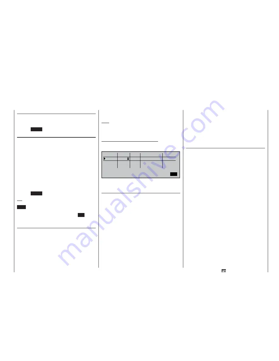
Column 5 “-time+”
A delay within the range 0 to 9.9 sec. can be pro-
grammed for all function inputs 5 … 12, either sym-
metrically or asymmetrically, in a similar manner to
the facilities in the »
Stick mode
» menu (see page
76). Use the rotary control to select
SYM
or
ASY
in
the right-hand column, then press the rotary control.
If you opt for an asymmetrical delay setting, you must
move the transmitter control in question to the appro-
priate end-point (or move the switch in the correct di-
rection), so that you can set the delay separately for
each side of neutral using the rotary control.
Note:
Please refer to the section entitled “Controlling timed
sequences” on page 182 for more ideas on how to
use sequences of this type.
Application: “retractable undercarriage:
•
Extend:
slow
•
Retract:
fast (or vice versa)
0% +100%+100%
+100%
offset
SEL
ASY
SYM
SYM
SEL
–
–time+
0%
0%
0%
+100%+100%
+100%+100%
+100%
0.0 0.0
2.5 0.0
0.0 0.0
0.0 0.0
«Normal »
ASY
7
Thr.l
Input
Input
Input
Cnt.
9
free
free
9
10
11
12
You can check the result of your settings by calling up
the »
Servo display
« menu.
“Throt 6” line
In the Helicopter program it is also possible in princip-
le to assign any of the transmitter controls (rotary pro-
portional controls, INC / DEC buttons) and switches
to the individual inputs.
However, please note here that some of the inputs
available in the »
Transmitter control adjust
” menu
are already assigned to helicopter-specifi c functions,
and therefore are not available for use in other ways.
For example, the receiver sequence table on page 43
shows that the throttle servo (or the speed control-
ler of an electric-powered helicopter) must always be
connected to receiver output “6”, as control channel
“6” is reserved for motor power control.
However, in contrast to a fi xed-wing model aircraft
the throttle servo or speed controller is not directly
controlled by the throttle stick or any other transmit-
ter control, but instead by a complex mixer system –
see the »
Helicopter mixers
« menu, starting on page
122. Moreover the “Throttle limit function” also has an
infl uence on this mixer system; this is described on
the next page.
Assigning a transmitter control or switch in the
“Throttle” line, or to its supplementary control signal,
would unnecessarily “confuse” this complex mixer
system.
For this reason the “Throttle” input MUST
be left set to “free”.
“Gyro 7” line
If the gyro you wish to use features proportional gain
(sensitivity) control, then its gyro effect can be pre-set
within the range +/-125% separately for each fl ight
phase; this is entered in the “Gyro” line of the »
Heli-
copter mixers
« menu.
The gyro gain settings should initially be selected se-
parately for each fl ight phase in the »
Helicopter mi-
xers
« menu. Based on these settings, gyro gain can
be varied using a transmitter control assigned in the
“Gyro 7” line of this menu; this could be one of the two
INC / DEC buttons CTRL 5 or 6; the centre position of
the transmitter control corresponds to the setting se-
lected in the »
Helicopter mixers
« menu (see page
122). If the transmitter control is moved from this cen-
tre point in the direction of full travel, gyro gain incre-
ases proportionally; it diminishes when moved in the
opposite direction. This arrangement provides a fast,
straightforward method of adjusting gyro gain to suit
changing weather conditions, even in fl ight, or to esta-
blish an optimum setting through fl ight-testing.
In software terms you can even limit the gyro gain
range in both directions by adjusting transmitter cont-
rol travel.
Summary of Contents for mx-24s
Page 1: ...1...
Page 19: ...19 For your notes...
Page 35: ...35 For your notes...
Page 41: ...41 41 For your notes...
Page 57: ...57 For your notes...
Page 63: ...63 63 For your notes...
Page 69: ...69 69 For your notes...
Page 85: ...85 85 For your notes...
Page 99: ...99 For your notes...
Page 143: ...143 For your notes...
Page 191: ...191 For your notes...
Page 212: ...212 212 For your notes...
Page 213: ...213 213 For your notes...
Page 214: ...214 For your notes...
Page 216: ...216...


