14
Operating notes
Operating notes
Adjusting stick length
Both sticks are infi nitely variable in length over a
broad range, enabling you to set them to the correct
length to suit your personal preference to provide fi ne,
accurate control of your models.
Loosen the retaining screw using a 2 mm allen key,
then screw the stick top in or out to shorten or extend
it. Carefully tighten the grubscrew again to lock the
set length.
Opening the transmitter case
Please read the following notes carefully before you
open the transmitter. If you are inexperienced in
such matters we recommend that you ask your local
GRAUPNER
Service Centre to carry out these proce-
dures for you.
The transmitter should only be opened in the follo-
wing circumstances:
• In order to convert a non self-neutralising stick to
self-neutralising, or vice versa; see page 16;
• In order to adjust the stick centring tension;
• In order to replace the internal fuse (3 A, fast-blow);
• In order to install a “Trainer” system and data trans-
fer system; see page 15 and page 204 of the Ap-
pendix.
Before opening the transmitter it is essential to check
that it is switched off (move the Power switch towards
the screen). It is not necessary to remove the trans-
mitter battery, but if you do not remove it take care ne-
ver to switch the transmitter on while the case is open
(“ON” position). Please see page 12 for information
on removing the transmitter battery. The RF module
can also be left in place.
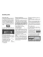
Use a cross-point screwdriver (size PH1) to undo the
six recessed screws
at the indicated
points in the rear
face of the trans-
mitter. Hold the two
case shells together
with your hand, turn
the transmitter over
and allow the six
screws to fall out.
The back cover can
now be carefully re-
moved.
Caution:
A loom of cables connects a circuit board in the
rear cover to the circuit board in the main case,
which means that the transmitter back cover can
only be folded down or to the side.
Important notes:
•
Do not modify the transmitter circuit in any
way, as this invalidates your guarantee and also
invalidates offi cial approval for the system.
•
On no account touch the circuit boards with
any metallic object, and do not touch the con-
tacts with your fi ngers.
•
Never switch the transmitter on when the case
is open.
When closing the transmitter please note the fol-
lowing points:
• Insert the two side-mounted proportional controls
correctly in the cut-outs designed for them in the si-
des of the transmitter case;
• You will fi nd two rubber pads fi tted loose in the si-
des; ensure that they are located with the small slot
facing the back cover, and engage them in the ap-
propriate case cut-outs in the sides;
• Ensure that the wire loom connector between the
back cover and the circuit board is fi rmly inserted;
• Check that the V-shaped spring contacts (earth
contacts) in the centre of the transmitter are not
bent or deformed.
• Take care that no wires get caught when you close
the back.
• Ensure that the two case shells line up exactly
fl ush before you fi t the retaining screws. Never
force the case shells together.
Please refer to the illustration on the next page when
you carry out this procedure.
Summary of Contents for mx-24s
Page 1: ...1...
Page 19: ...19 For your notes...
Page 35: ...35 For your notes...
Page 41: ...41 41 For your notes...
Page 57: ...57 For your notes...
Page 63: ...63 63 For your notes...
Page 69: ...69 69 For your notes...
Page 85: ...85 85 For your notes...
Page 99: ...99 For your notes...
Page 143: ...143 For your notes...
Page 191: ...191 For your notes...
Page 212: ...212 212 For your notes...
Page 213: ...213 213 For your notes...
Page 214: ...214 For your notes...
Page 216: ...216...


