67
Note:
If you operate virtually all your models using the same
stick mode, and perhaps also with the same modu-
lation, it makes sense to select these preset values
in the global »
General basic settings
« menu (page
154). These two presets are automatically adopted
when you open a free model memory, but you can still
change them to suit a particular model if you wish.
Autorotation
During an auto-rotation descent the main rotor is not
driven by the motor; it is kept spinning only by the air-
fl ow through the rotor plane caused by the speed of
the descent, in a similar manner to a windmill. The ro-
tational energy stored in the still spinning rotor can be
exploited to allow the machine to fl are out and be “sa-
ved”, but this can only be accomplished once.
Auto-rotation allows full-size and model helicopters
to land safely in a crisis, i. e. if the power plant should
fail. The pre-condition for a successful “auto” landing
is a well-trained pilot who is thoroughly familiar with
his fl ying machine. Fast reactions and a good eye are
also required, as the rotational energy in the rotor can
only be used once to fl are out.
When the auto-rotation manoeuvre is called at a com-
petition, the motor must be stopped. However, for
practice purposes it is advantageous to keep the mo-
tor running at idle when you are practising this mano-
euvre, so that you can apply full-throttle instantly if a
critical situation should arise.
The auto-rotation switch is used to switch to the auto-
rotation fl ight phase, in which the controls for “Thrott-
le” and “Collective pitch” are separated, and all mixers
which include the throttle servo are switched off. The
associated parameters are set in the »
Helicopter mi-
xers
« menu (see page 122); see also the following
section “How Autorot C1 Pos. works”.
This fl ight phase is assigned the name “Autorot”,
which cannot be changed. It is included in the basic
display and in all fl ight phase dependent menus (see
page 98 for list).
Defi ning the auto-rotation switch
Press the rotary control and assign a switch to this
function as described on page 32.
This switch has
absolute priority over all other fl ight phase swit-
ches.
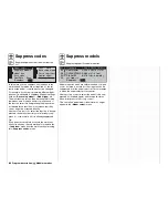
Autorot. C1 position
Alternatively the auto-rotation fl ight phase can be ac-
tivated by setting a switching point on the throttle /
collective pitch stick C1. If you select this line on the
screen, the memory fi eld
STO
appears.
Move the C1 stick to the desired switching position,
and press the rotary control: the current value is dis-
played. The task is completed by assigning an activa-
tion switch in the right-hand column.
If you operate (close) this activa-
tion switch, the program switches
to “Auto-rotation” as soon as the stick is moved be-
low the set switching point, and remains in this fl ight
67
Program description:
Basic settings
phase, regardless of the C1 position, until the activa-
tion switch – in our example No. 2 – is moved back to
“OFF”.
“Auto-rotation C1 pos.” has priority over all other
fl ight phase switches.
The associated parameters for
• collective pitch servos
• throttle
servo
• tail rotor servo
• any set swashplate rotation
• and gyro adjustment
are adjusted in the »
Helicopter mixers
« menu (see
page 122).
All other menus relating to auto-rotation are grouped
together in the table on page 98.
Marker key
When you operate the marker button in the “Collecti-
ve pitch” curve, and in the “Channel 1
throttle” and
“Channel 1
tail rotor” mixer curves in the »
Helicop-
ter mixers
« menu, a marker is placed at the current
collective pitch stick position in the form of a dotted
line. This marker is helpful when it comes to placing
curve points, e. g. the hover point, at the correct posi-
tion during fl ight-testing.
A switch must be assigned, preferably the momenta-
ry switch SW8.
Example:
You may be aiming to place the hover point at the
centre of the throttle / collective pitch stick in the “Ho-
ver” fl ight phase, but fi nd during fl ight-testing that the
hover point is still above the centre point of the stick
travel. Press the marker switch in this position, and
then look at the collective pitch curve in the »
Helicop-
ter mixers
« menu (see page 122) once you have lan-
ded the model again:
Approach angles in
varying wind con-
ditions.
45°
60°
75°
Approach angle::
In strong
wind
In moderate
wind
In calm conditions
Move the C1 stick to
the desired position
SIC SETTINGS, MODEL
de
n
SPCM20
C1 Pos.
on
1
STO
–85%
2
Summary of Contents for mx-24s
Page 1: ...1...
Page 19: ...19 For your notes...
Page 35: ...35 For your notes...
Page 41: ...41 41 For your notes...
Page 57: ...57 For your notes...
Page 63: ...63 63 For your notes...
Page 69: ...69 69 For your notes...
Page 85: ...85 85 For your notes...
Page 99: ...99 For your notes...
Page 143: ...143 For your notes...
Page 191: ...191 For your notes...
Page 212: ...212 212 For your notes...
Page 213: ...213 213 For your notes...
Page 214: ...214 For your notes...
Page 216: ...216...


