159
Programming examples: Fixed-wing model
cular model.
At this point, just before you start programming the
model data, it is worthwhile thinking carefully about a
sensible layout of the transmitter controls.
If the model in question is one with the emphasis on
“power” – whether the power of an electric motor or
an internal combustion engine – you will probably en-
counter few problems in this matter, because the two
dual-axis stick units are primarily employed to cont-
rol the four basic functions “power control (= throttle)”,
“rudder”, “elevator” and “aileron”. Nevertheless, you
still have to call up the ...
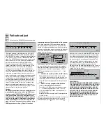
»Model type« (page 70)
SEL
Offset
+100%
Thr. min back
M O D E L T Y P E
Tail type
Aileron/camber flaps
Brake
Input 1
Normal
1 AIL
Motor on C1
… and defi ne your preferred throttle direction, i. e.
throttle minimum “forward” or “back”, because the de-
fault setting is “none” (i. e. no motor).
The difference between “none” and “Throttle min. for-
ward / back” is the effect of the C1 trim. The trim is ef-
fective over the full stick travel if “none” is entered, but
it affects the idle range only if you enter “throttle min.
forward / back”.
However, this setting also takes the “direction of ef-
fect” of the C1 stick into account, so that you do not
need to change the direction of rotation of the thrott-
le servo if you switch from “forward” to “back”. If you
change the setting of “Throttle min. forward / back”,
you activate a warning message on the screen …
… and you will hear a warning beep if you switch on
the transmitter with the throttle stick too far in the di-
rection of full throttle.
You will certainly want to consider carefully how best
to control any “auxiliary functions” included in your
model, for example the programming of an (additio-
nal) power-on warning in the »
Base setup model
«
menu (page 64). Such a warning does not, of course,
need to signal just “Throttle too high” or “Motor is on”;
it could just as well warn you of “Undercarriage re-
tracted” or similar. Give this some thought, and allow
your imagination plenty of scope.
In contrast, if your model is a glider or electric glider
the whole situation may be rather different. The im-
mediate question is: what is the best way of operating
the motor and braking system? Some solutions have
proved to be highly practical, and others less so.
For example, it is not a good idea to be forced to
let go of one of the primary sticks in order to ex-
tend the airbrakes or deploy the crow braking system
when your glider is on the landing approach. It sure-
ly makes more sense to set up switchable functions
for the C1 stick (see the programming examples on
page 167 and 169), or to assign the braking system
to the stick, and shift the motor control to a slider – or
even a switch. With this type of model the electric mo-
tor is often little more than a “self-launching system”,
and is used either to drag the model into the sky at
full power, or to pull it from one area of lift to the next
at, say, half-power; for such models a three-position
switch is usually quite adequate. If the switch is positi-
oned where you can easily reach it, then you can turn
the motor on and off without having to let go of the
sticks – even on the landing approach. The
mx
-24s
provides plenty of scope for your ideas here.
Incidentally, similar thinking can be applied to fl ap
control systems, regardless of whether they are “just”
the ailerons, or full-span (combination) control sur-
faces which are raised and lowered in parallel.
To control the electric motor all you need is one of the
two-position switches SW 1 … 4 or 7, or – better –
one of the two three-position switches CON TROL 7 or
8. In any case please be sure to select a switch which
is close to the sticks, so that you can reach it at any
time without having to let go of the primary controls.
This switch should also be positioned on the side of
the transmitter opposite to the hand which holds the
model when hand-launching. In other words: if you
use your right hand to launch the model, the switch
which you select to control the motor should be on
the left-hand side of the transmitter, and vice versa.
Camber-changing fl aps can also be controlled very
effectively by means of one of the three-position swit-
ches (CTRL 7 or SW 5 + 6 or CTRL 8 or SW 9 + 10),
or alternatively one of the two INC / DEC buttons
CONTROL 5 or 6. The advantage of these latter con-
trols is that their positions are stored separately for
each fl ight phase, and are therefore not lost when you
switch fl ight phases or models; this is not the case
with the side-mounted proportional controls.
Once you are satisfi ed that all these preparations
have been completed successfully, you are ready to
start programming.
Thr
too
high!
Summary of Contents for mx-24s
Page 1: ...1...
Page 19: ...19 For your notes...
Page 35: ...35 For your notes...
Page 41: ...41 41 For your notes...
Page 57: ...57 For your notes...
Page 63: ...63 63 For your notes...
Page 69: ...69 69 For your notes...
Page 85: ...85 85 For your notes...
Page 99: ...99 For your notes...
Page 143: ...143 For your notes...
Page 191: ...191 For your notes...
Page 212: ...212 212 For your notes...
Page 213: ...213 213 For your notes...
Page 214: ...214 For your notes...
Page 216: ...216...


