153
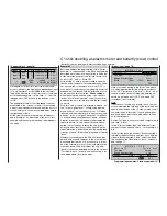
Program description:
Special functions
For maximum fl exibility in terms of receiver socket as-
signment, the
mx
-24s program provides a means of
swapping over the servo outputs 1 to max. 12.
With this option you can distribute the transmitter’s
twelve “control channels” to any of the receiver out-
puts, i. e. to servo sockets 1 … 12 respectively. Ho-
wever, please note that the display in the »
Servo dis-
play
« menu refers exclusively to the “
Control chan-
nels
”, i. e. it
does not
take any interchanged outputs
into account.
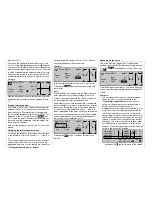
R E C E I V E R O U T P U T
S e r v o
S e r v o
S e r v o
S e r v o
SEL
O u t p u t
1
2
3
4
O u t p u t
O u t p u t
O u t p u t
1
2
3
4
Hold the rotary control pressed in to select the line of
the servo / output combination you wish to change.
After a brief press on the rotary control you can now
assign the desired “servo” to the selected “recei-
ver” output using the rotary control in the highligh-
ted fi eld … or restore the default assignment by pres-
sing
CLEAR
. Any subsequent changes, such as ser-
vo travel adjustments, Dual Rates / Expo, mixers etc.,
must still correspond to the original receiver as-
signment!
Typical applications:
•
If you wish to use a small receiver with six or even
just four servo sockets, it may be necessary to
swap over the receiver sockets in order to operate
a second camber-changing fl ap, a second aileron
servo or a speed controller.
•
If you are using a model set up for another make*
of equipment, it may also prove necessary to swap
servos for Trainer mode operations, to avoid ha-
ving to re-connect the servos at the receiver.
•
In the helicopter program of the
mx
-24s the out-
puts for one collective pitch servo and the thrott-
le servo have been interchanged compared to cer-
tain earlier GRAUPNER/JR
mc
-systems:
The throttle servo is now assigned to receiver out-
put “6” and the collective pitch servo to output “1”.
You may therefore wish to retain the earlier confi -
guration. In this case you will need to program out-
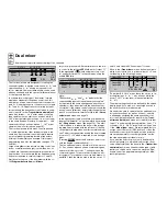
puts 1 and 6 as shown in the screen-shot printed
below:
Notes:
• If you wish to swap over the receiver outputs, ple-
ase remember that the Fail-Safe programming
“Hold” and “Pos.” in SPCM and APCM mode al-
ways refers to the “outputs”, i. e. the receiver’s so-
cket numbers.
• Note also that the servo position displays in the
»
Servo display
« menu also refer to the “servo
number” or “control channel number”, and not to
the receiver outputs, which you may have chan-
ged.
* GRAUPNER does not guarantee that GRAUPNER radio cont-
rol systems will work correctly in conjunction with receiving sys-
tems and radio control equipment made by other manufacturers.
S e r v o
6
S e r v o
2
S e r v o
3
S e r v o
4
S e r v o
5
S e r v o
1
6
SEL
R E C E I V E R O U T P U T
O u t p u t
1
2
3
4
O u t p u t
O u t p u t
O u t p u t
5
O u t p u t
O u t p u t
Rx. output swap
Altering the servo sequence
the Teacher module, and the plug marked “S” (Stu-
dent) to the Pupil module.
The individual functions to be transferred are selected
in the Teacher transmitter’s »
Teacher/pupil
« menu
(see page 150), which can be operated in any of the
following modes: PPM10, PPM18, PPM24, PCM20,
SPCM20 or APCM24.
Suitable Pupil transmitters
D 14, FM 414, FM 4014, FM 6014,
mc
-10,
mc
-12,
mx
-12
mc
-14,
mc
-15,
mc
-16,
mx
-16s,
mc
-16/20,
mc
-17,
mc
-18,
mc
-19,
mc
-20,
mc
-22,
mc
-22s,
mx
-22,
mc
-24 and
mx
-24s.
The Pupil transmitter must always be set to operate in
PPM mode.
If you are using an
mc
-series or
mx
-series trans-
mitter, it is best to activate a free model memory and
use that memory in its base setting, with the appropri-
ate model type (“Fixed-wing” or “Helicopter”) selected.
Assign the name “Pupil” to this memory, and set up
the stick mode (Mode 1 … 4) to suit the pupil’s prefe-
rence. All other settings should be left at their default
values. If you select the “Fixed-wing” model type it is
permissible to set “Throttle forward / back” in the “Mo-
tor” line of the »
Model type
« menu. If you have se-
lected the “Helicopter” model type, you must also set
the throttle / collective pitch direction and idle trim on
the Pupil transmitter. All other settings, including mi-
xer and coupling functions, are entered exclusively at
the Teacher transmitter, which in turn transfers them
to the model.
If you are using one of the following transmitters: D14,
FM414, FM4014, FM6014, FM6014 / PCM 18, you
must also check the direction of servo rotation and
stick mode, and make corrections if necessary by re-
connecting the leads inside the transmitter. All other
mixers must be switched off or set to “zero”.
Summary of Contents for mx-24s
Page 1: ...1...
Page 19: ...19 For your notes...
Page 35: ...35 For your notes...
Page 41: ...41 41 For your notes...
Page 57: ...57 For your notes...
Page 63: ...63 63 For your notes...
Page 69: ...69 69 For your notes...
Page 85: ...85 85 For your notes...
Page 99: ...99 For your notes...
Page 143: ...143 For your notes...
Page 191: ...191 For your notes...
Page 212: ...212 212 For your notes...
Page 213: ...213 213 For your notes...
Page 214: ...214 For your notes...
Page 216: ...216...


