180
180
Programming examples: Fixed-wing model
Note:
The FLAP and AILE positions at the two switch end-
points and the switch centre position refl ect the va-
lues set in the “-” column, the Offset value, and
the mixer ratio which you have set in the “Multi-fl ap
menu” of the »
Wing mixers
« menu.
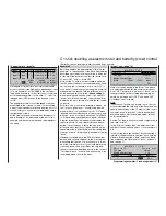
For our purposes we will leave the transmitter cont-
rol “travel” at a symmetrical setting of +100%, and the
Offset value at 0%, as shown in the screen-shot.
However, it is advisable to enter a
SYM
metrical or
ASY
mmetrical time for a smooth transition between
the three switch positions. This is entered in the
“-time+” column; in our example the value is set to
“1.0 s 1.0 s”:
0%
+
100%+100%
0% +100%+100% 0.0 0.0
0% +100%+100% 0.0 0.0
ASY
SYM
SEL
SEL
ASY
0.0 0.0
SYM
Cnt. 6
–time+
offset
0% +100%+100%
1.0 1.0
«Thermal»
free
8
7
6
5
Input
Input
Input
Input
free
free
–
In the “Multi-fl ap menu” of the menu …
»Wing mixers« (page 110)
+100%
+ 60%
Diff.
+ 50%
+ 30%
+ 10%
+ 15%
+10% +10%
0% 0%
0%
0%
AILE
SYM
ASY
+100%
FLAP
+ 60%
+15% +15%
«Thermal»
SYM
ASY
AI
Ail–tr
Fl.pos
FL
El–>Fl
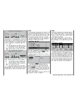
… you should now change the values for “Fl.pos” and
“
FL
” in the “Thermal” fl ight phase:
Fl.pos
:
In this line you defi ne the AILE and FLAP
positions in the “Thermal” fl ight phase for
the neutral of centre position of the assig-
ned transmitter control (proportional con-
Phase to
1 Normal
2 Thermal
YES
NO
–
to be copied?
You can now repeat the whole procedure with the
fl ight phase “3 Speed”.
At this point we will enter the changes required in
the “Thermal” fl ight phase, as an example of the
procedure.
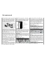
To vary the fl ap settings in the “Thermal” phase you
simply move to the menu …
»Control adjust« (pagee 78)
… and assign a transmitter control to input 6, as de-
scribed on page 78.
If you assign one of the two side-mounted proportio-
nal controls to this input, or one of the two INC / DEC
buttons (in our example CONTROL 6) you can fi ne-
tune the travels of the ailerons (2 + 5) and the fl aps (6
+ 7) by setting the mixer ratios in the »
Wing mixers
«
menu.
0%
+
100%+100% 0.0 0.0
0% +100%+100% 0.0 0.0
0% +100%+100% 0.0 0.0
0% +100%+100% 0.0 0.0
ASY
SYM
SEL
«Thermal»
Cnt. 6
SYM ASY
SEL
free
–time+
offset
8
7
6
5
Input
Input
Input
Input
free
free
–
If you assign another free three-position switch to In-
put 6 instead, you can use it to call up three diffe-
rent fl ap positions for the ailerons (AILE) and fl aps
(FLAP), and three elevator positions (EL) in the
“Thermal” fl ight phase; see the following page. (These
three switch positions correspond to the centre posi-
tion and the two end-points of the side-mounted pro-
portional control mentioned above.)
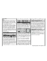
This is achieved by calling up the menu …
»Copy / Erase« (page 60)
… and selecting the “Copy fl ight phase” line:
=>
=>
=>
=>
=>
Erase model
Copy model –>
model
Copy MX24 –>
external
Copy external –> MX24
Copy flight phase
In “Copy from phase” you will see all eight possible
fl ight phases listed:
1. Select the fl ight phase you wish to copy, i. e.
“1 normal”.
1 Normal
2 Thermal
3
5
7
6
8
4
Speed
Copy
from Phase:
2. Give the rotary control a brief press (or press
EN-
TER
) to move to the “Copy to phase” window for
entering the destination memory.
3. Select the phase “2 Thermal” as destination:
1 Normal
3
5
7
6
8
4
Speed
2 Thermal
Copy
to Phase:
4. Confi rm this with a brief press on the rotary cont-
rol, or by pressing
ENTER
.
5. The screen now presents you with a security que-
ry, which you should confi rm with “YES”:
Summary of Contents for mx-24s
Page 1: ...1...
Page 19: ...19 For your notes...
Page 35: ...35 For your notes...
Page 41: ...41 41 For your notes...
Page 57: ...57 For your notes...
Page 63: ...63 63 For your notes...
Page 69: ...69 69 For your notes...
Page 85: ...85 85 For your notes...
Page 99: ...99 For your notes...
Page 143: ...143 For your notes...
Page 191: ...191 For your notes...
Page 212: ...212 212 For your notes...
Page 213: ...213 213 For your notes...
Page 214: ...214 For your notes...
Page 216: ...216...


