44
Brief programming instructions
for all fi xed-wing and helicopter programs
Brief programming instructions
Memories
Memories
•
•
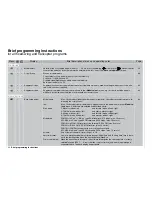
Model select
Selects a free or occupied model memory 1 … 40. An icon for fi xed-wing (
) or helicopter (
) makes it easier
to select the model, as does the information entered in the “Info” line of the »
Base setup model
« menu.
59
•
•
Copy / Erase
Erase a model memory
Copy contents of one model memory to another memory
Copy from / to
mx
-24s and PC
Copy individual fl ight phases within one model memory
Back-up all models to a PC
60
•
•
Suppress Codes
Suppress functions from the multi-function select list within a memory; used for settings which are not to be alte-
red, or which are not required.
62
•
•
Suppress models
Suppress model memories from the list shown in the »
Model select
« menu, e. g. in order to exclude models
which are not in airworthy condition; also makes the list easier to use.
62
Basic settings
Basic settings
•
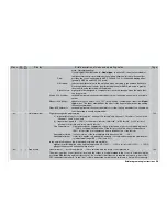
Base setup model
Model name:
Max. 10 characters (letters, numbers, special symbols). Characters are selected from a ta-
ble using the rotary control.
Info:
Max. 15 characters per model memory. Appears next to the model name in the »
Model se-
lect«
menu. Characters are selected as described above.
Stick mode:
1: Elevator, rudder: left
and throttle / brake, aileron: right
2: Throttle / brake, rudder: left
and aileron, elevator: right
3: Aileron, elevator: left
and throttle / brake, rudder: right
4: Throttle / brake, aileron: left
and elevator, rudder: right
Modulation:
PCM20 for all “mc” or “DS mc” type PCM receivers (512 steps / max. 10 servos)
SPCM20 for all “smc” type SPCM receivers (1024 steps / max. 10 servos)
PPM18 for all PPM-FM receivers to date except DS 24 FM (max. 9 servos)
PPM24 for “DS 24 FM S” PPM FM receiver (max. 12 servos)
PPM10 for PPM-FM receivers with no more than fi ve outputs
APCM24 for all “amc” type APCM receivers (1024 steps / max. 12 servos)
Volume:
Vary volume of the alarm timer, range 1 to 16.
Auto timer reset:
Yes / no determines whether all timers (except “Model time” and “Battery time”) are to be re-
set to the starting value when the transmitter is switched on.
Power-on warning:
When the transmitter is turned on, the software interrogates the switched state of a freely
selectable switch (SW 1 … 8, control switch or logical switch), and a warning message is
superimposed on the basic display if appropriate.
64
Display
Menu
Brief description of menu and operating notes
Page
Summary of Contents for mx-24s
Page 1: ...1...
Page 19: ...19 For your notes...
Page 35: ...35 For your notes...
Page 41: ...41 41 For your notes...
Page 57: ...57 For your notes...
Page 63: ...63 63 For your notes...
Page 69: ...69 69 For your notes...
Page 85: ...85 85 For your notes...
Page 99: ...99 For your notes...
Page 143: ...143 For your notes...
Page 191: ...191 For your notes...
Page 212: ...212 212 For your notes...
Page 213: ...213 213 For your notes...
Page 214: ...214 For your notes...
Page 216: ...216...


