22
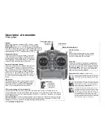
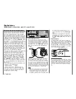
Description of screen
ENTER
(Input button):
Switches to multi-function list
Calls up a menu
ESC
(Escape button):
Returns step by step from any
menu to the basic display
CLEAR
(Erase button):
Resets altered values to default
settings
HELP
(Help button):
Calls up a brief help message re-
lating to any menu
Model name
(max. 10 characters)
Model memory
1 … 40
User’s name
(max. 15 characters)
Model ope-
rating time
Superimposed warning messages*
Stopwatch in min:sec
(count-up / count-down)
Flight time in min:sec
(count-up / count-down)
Battery voltage, shown by a dynamic bar
display. If the battery voltage falls below a
particular (selectable) threshold (see page
155), a warning appears on the screen ac-
companied by an audible alert signal.
Transmit-
ter operating
time. This is
automatically
reset to zero
when the bat-
tery is rechar-
ged.
Display diagram for all four digital trim levers with numerical and direction indicators: “
”
or “
”. Special cut-off trim for C1 (see page 34).
For each trim lever separately the “shadow” indicates whether the trim operates glo-
bally (= shadow) or separately for each fl ight phase (this parameter is set in the »
Stick
mode
« menu, see pages 76 / 77). Exception: the C1 trim always operates globally.
The rotary control can be
operated on two levels.
At the basic transmitter
display it is used to ad-
just screen contrast when
held pressed in, or:
Press the rotary control
and adjust screen cont-
rast using CTRL 5 or 6 –
unless these buttons are
already assigned to ano-
ther function.
GRAUPNER logo, alternatively the fl ight pha-
se name. Different fl ight phases are selected
by operating user-assigned switches.
Description of screen
Batt must
be re-
charged!!
Charge battery*
Current
channel
number.
The num-
ber fl as-
hes if the
RF module
is switched
off.
(Note: an additional timer
can also be activated.)
Model type
Fixed-wing or
Helicopter
Notes:
* If the transmitter battery voltage is too low, the message “Currently not possible,
battery voltage too low” appears in the »
Model select
« and »
Copy / Erase
« me-
nus.
** For safety reasons this warning can only be disabled for non-powered fi xed-wing
models: in this case select the »
Model type
« menu (see page 70) and enter
“none” in the “Motor” line.
Unlock by
rotary
and CLR
Button pad lock
Button pad lock
Hold rotary control pressed in +
CLEAR
button.
Thr
too
high!
Throttle stick too
advanced**
No
pupil
signal
Problem with
Trainer mode
Fail Safe
setup
t.b.d.
Only in PCM20,
SPCM20 and
APCM24 modes
!Warning!
Power-on war-
ning for selectab-
le switch
Summary of Contents for mx-24s
Page 1: ...1...
Page 19: ...19 For your notes...
Page 35: ...35 For your notes...
Page 41: ...41 41 For your notes...
Page 57: ...57 For your notes...
Page 63: ...63 63 For your notes...
Page 69: ...69 69 For your notes...
Page 85: ...85 85 For your notes...
Page 99: ...99 For your notes...
Page 143: ...143 For your notes...
Page 191: ...191 For your notes...
Page 212: ...212 212 For your notes...
Page 213: ...213 213 For your notes...
Page 214: ...214 For your notes...
Page 216: ...216...

