94
Control switch
Programming control switches
Program description: Switches
C O N T R O L S W I T C H
G1
Cnt.
–75%
G2
G3
G4
SEL
free
=>
G1
+75%
=>
0%
=>
0%
=>
G2
G3
G4
Cnt.
STO
SEL
1
1
free
Many auxiliary functions are best controlled automati-
cally by a particular (freely programmable) position of
a transmitter control or stick, rather than by a conven-
tional switch.
Typical applications:
• Switching an on-board glowplug energizer on
and off according to the throttle position or motor
speed. In this case the switch for the plug energi-
zer is controlled by a mixer at the transmitter.
• Switching a stopwatch on and off in order to time
the motor run of an electric motor.
• Switching a “combi-switch” mixer (coupled aile-
ron / rudder, “Aileron 2
4 rudder”) on and off au-
tomatically when airbrakes are extended, for ex-
ample, to allow you to match the model’s angle
of bank to the slope of the ground when landing
on a ridge, as the mixed rudder would affect the
model’s heading if the mixer were still active.
• Changing various settings on the landing ap-
proach when the throttle stick is reduced below a
pre-set switching point; the settings could be: lo-
wering landing fl aps, altering the elevator trim, and
/ or triggering specifi c Dual Rate, Exponential and
Differential settings. In column 5 a switch can also
be assigned separately, to allow you to disable /
activate the control switch.
The
mx
-24s program features eight of these control
switches, designated G1 to G8, of which the two fi rst
ones are already assigned as follows: by default G1 is
triggered at -75% and G2 at +75% of the travel of the
C1 stick (throttle / brake or throttle / collective pitch).
G1 and G2 can therefore be included without restric-
tion in the free programming of the switches, i. e. they
can be assigned to a function.
The software gives you the opportunity to assign
switches at all points in the program where their use
makes sense. At these points you can select and as-
sign one of a maximum of ten transmitter switches or
one of the control switches G1 … G8 simply by ope-
rating the switch or moving the transmitter control to
which a control switch is assigned. In this case the di-
rection of switching is always determined by the di-
rection of movement, i. e. when you move the approp-
riate switch or transmitter control, the software
always
interprets the new position, i. e. the one to which you
move it in order to assign it, as the ON setting.
The control switches can be used in combination with
a separate switch (see below) to generate more com-
plex switch combinations.
The basic procedure:
1. If no transmitter control is assigned, only one
SEL
fi eld will be displayed in the bottom line of the
screen.
2. Hold the rotary control pressed in, and select the
control switch 1 to 8 you wish to use.
3. Press the rotary control briefl y.
4. Move the appropriate transmitter control.
5. Press the rotary control to conclude the select pro-
cedure.
6. You will now see additional fi elds (
STO
,
SEL,
)
which you can select by turning the rotary control.
7. Move the transmitter control to the desired swit-
ching point.
8. Press the rotary control.
9. Select the setting using the rotary control.
10. Press the rotary control to end the input procedu-
re.
11. Press the
ESC
button to leave the menu.
Assigning a transmitter control to a control
switch
Select the appropriate line 1 to 8 with the rotary con-
trol pressed in. After another brief press on the ro-
tary control (to activate transmitter control assign-
ment), the following message is superimposed on the
screen:
Cnt.
–75%
SEL
free
=>
+75%
=>
0%
=>
0%
=>
Cnt.
Move desired
free
C O N T R O L S W I T C H
control adj.
G1
G2
G3
G4
G1
G2
G3
G4
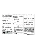
For our example we will now assign the right-hand
side-mounted proportional control (CONTROL 9) to
the control switch “G3”. Move this control from for-
ward to back (G3 is to be closed when the throttle li-
miter releases the throttle). As soon as this is detec-
ted, additional fi elds appear at the bottom edge of the
screen:
SEL
–75%
=>
+75%
=>
0%
0%
=>
=>
STO
SEL
Cnt.
1
1
9
C O N T R O L S W I T C H
G1
Cnt.
G2
G3
G4
G1
G2
G3
G4
Cnt.
free
Important note:
The two INC / DEC buttons (Controls 5 and 6) can
only be assigned to a control switch if they have PRE-
VIOUSLY been assigned to an input in the »
Trans-
mitter control adjust
« menu.
Summary of Contents for mx-24s
Page 1: ...1...
Page 19: ...19 For your notes...
Page 35: ...35 For your notes...
Page 41: ...41 41 For your notes...
Page 57: ...57 For your notes...
Page 63: ...63 63 For your notes...
Page 69: ...69 69 For your notes...
Page 85: ...85 85 For your notes...
Page 99: ...99 For your notes...
Page 143: ...143 For your notes...
Page 191: ...191 For your notes...
Page 212: ...212 212 For your notes...
Page 213: ...213 213 For your notes...
Page 214: ...214 For your notes...
Page 216: ...216...


