175
175
Programming examples: Fixed-wing model
A
B
C
D
E
F
<1
>
SEL
5
6
Normal
P H A S E A S S I G N M E N T
p r i o r
combi
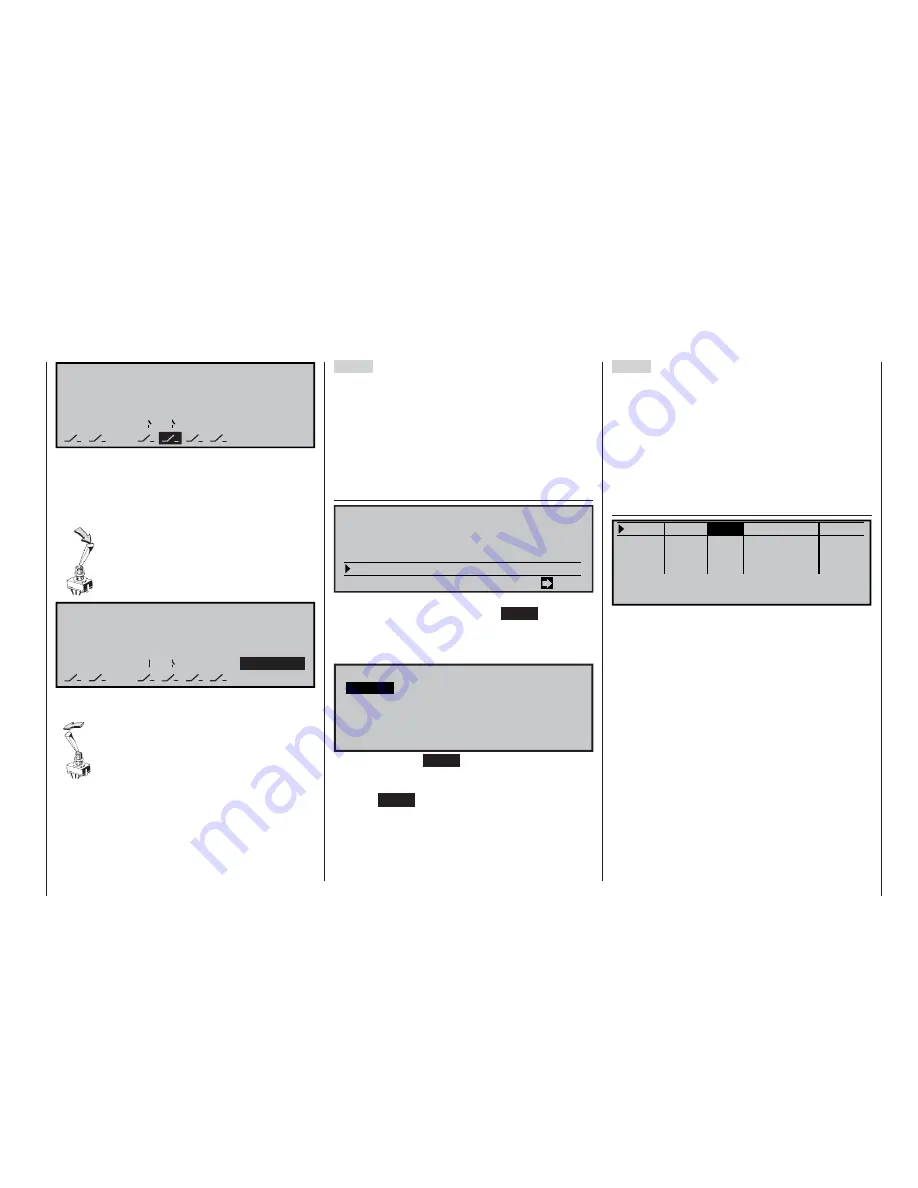
The phase switch is now programmed correctly, and
the next step is to assign fl ight phases to each switch
position. Although you have already assigned names
to certain fl ight phases, you will initially see the name
of phase “1” (normal) on the right-hand side of the
screen.
Move the switch to one end-point, and se-
lect the
SEL
fi eld on the right of the screen.
Use the rotary control to select the fl ight
phase you wish to assign to this switch po-
sition (in this example «2 Thermal»):
A
B
C
D
E
F
<
5
6
SEL
Thermal
2
>
P H A S E A S S I G N M E N T
p r i o r
combi
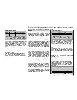
Repeat the procedure with the centre position of the
switch, to which the name “1 normal” is assigned.
Finally assign the name “3 Speed” to the
opposite end-point of the switch. A brief
press on the rotary control concludes the
name assignment process.
The model settings you programmed be-
fore you assigned the phase switch are now stored in
the fl ight phase “1 normal”; that is the phase which is
called up when the switch is at the centre position.
Step 3
You have already programmed all the settings for your
model in the primary fl ight phase, and you can avo-
id having to enter all the data again in the “new” fl ight
phases by copying the programmed settings – which
you know from test-fl ying to be correct – from the
“normal” fl ight phase into the other two fl ight phases,
where they will be adjusted to suit the new require-
ments. This is carried out in the menu:
»Copy / Erase« (page 60)
=>
=>
=>
=>
=>
Erase model
Copy model –>
model
Copy MX24 –>
external
Copy external –> MX24
Copy flight phase
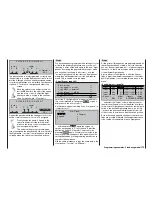
Select the “Copy fl ight phase” menu point with the ro-
tary control pressed in, then press
ENTER
or give a
brief press on the rotary control.
A window now appears entitled “Copy from phase”; in
it select “normal” ...
Copy
1 Normal
2 Thermal
3
5
7
6
8
4
Speed
from Phase:
… and then press
ENTER
again; the screen re-
sponds by changing to “Copy to phase”. Select the
destination (initially “2 Thermal”), and confi rm by
pressing
ENTER
again. Confi rm your selection in the
security query which appears, then wait while all the
settings defi ned by your programming procedure are
copied to the new phase.
Use the same procedure to copy the same data to the
other phase (“1 normal”
“3 Speed”).
Step 4
At this point all three phases are programmed and all
the settings have been copied; a “smooth” transition
has also been programmed, but ... all the settings are
the same, i. e. there are no values which are specifi c
to the different fl ight phases.
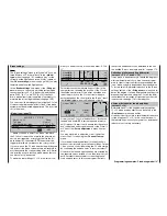
A good place to start might be to alter the fl ap set-
tings to meet the different requirements of the indivi-
dual fl ight phases; to accomplish this we move to the
menu …
»Control adjust« (page 78)
+
100%+100% 0.0 0.0
0% +100%+100% 0.0 0.0
0% +100%+100% 0.0 0.0
0% +100%+100% 0.0 0.0
SYM ASY
ASY
SYM
SEL
SEL
«Speed »
–7%
–time+
offset
Input 5
free
Input 6
Input 7
Input 8
free
free
free
–
… and select the “Offset” column, where you enter
the aileron settings in so far as they differ from those
in the “normal” fl ight phase. However, do remember to
switch to the desired fl ight phase before you do this;
i. e. check the phase name displayed at bottom left
of the screen, in accordance with the switch position.
Both positive and negative changes to the travel set-
tings are possible. Naturally, these adjustments have
to be carried out separately for each fl ight phase.
Summary of Contents for mx-24s
Page 1: ...1...
Page 19: ...19 For your notes...
Page 35: ...35 For your notes...
Page 41: ...41 41 For your notes...
Page 57: ...57 For your notes...
Page 63: ...63 63 For your notes...
Page 69: ...69 69 For your notes...
Page 85: ...85 85 For your notes...
Page 99: ...99 For your notes...
Page 143: ...143 For your notes...
Page 191: ...191 For your notes...
Page 212: ...212 212 For your notes...
Page 213: ...213 213 For your notes...
Page 214: ...214 For your notes...
Page 216: ...216...


