139
Program description:
Mixers
(You can reset the mixer neutral point to centre auto-
matically by selecting
CLR
.)
Symmetrical mixer ratios
The next step is to defi ne the mixer values above and
below the mixer neutral point, starting from the cur-
rent position of the mixer neutral point. Select the
SYM
fi eld, so that the mixer value can be set sym-
metrically relative to the offset point we have just pro-
grammed. Press the rotary control briefl y, then set the
values in the two left-hand highlighted fi elds within the
range -150% to +150%. Remember that the set mi-
xer value always refers to the control signal which is
passed to the mixer! Setting a negative mixer value
reverses the direction of the mixer, while pressing the
CLEAR
button erases the mixer ratio.
The “optimum” value for our purposes will inevitab-
ly need to be established through a fl ight testing pro-
gramme.
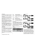
+ 2 0 % + 2 0 %
+ 7 5 %
m
OU
T
P
U
T
--
+
100
STO
ASY
SYM
CLR
6
Linear MIX 1
Mix input
EL
O f f s e t
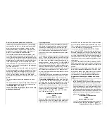
Since we earlier set the mixer neutral point at +75%
of control travel, the elevator “EL” will already exhibit
a (slight) down-elevator effect at the neutral point of
the landing fl aps, and this, of course, is not wanted.
To avoid this problem we shift the mixer neutral point
back to 100% control travel, as described earlier.
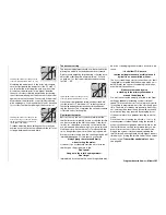
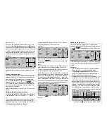
If you were now to reset the offset from 75% to, say,
0% control travel, the screen would look like this:
+ 2 0 % + 2 0 %
0 %
m
OU
T
P
U
T
--
+
100
STO
ASY
SYM
CLR
6
Linear MIX 1
Mix input
EL
O f f s e t
Asymmetrical mixer ratios
For many applications, however, we need to set up
different mixer values on either side of the mixer neu-
tral point.
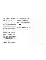
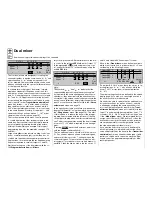
If you select the
ASY
fi eld and (in our example) move
the side-mounted proportional control in one direc-
tion, the mixer ratio for each direction of control can
be set separately:
+25%
+50%
0%
m
OU
T
P
U
T
-
+
100
STO
ASY
SYM
CLR
6
Linear MIX 1
Mix input
EL
O f f s e t
Note:
If you are setting up a switch channel mixer of the
“S
…” type you must operate the assigned switch
to achieve this effect. The vertical line then switches
between the left and right sides.
Setting the curve mixers 9 … 12
These four curve mixers enable you to defi ne ex-
tremely non-linear mixer curves by placing up to six
(freely positionable) points between the two end-
points “L” (low = -100% control travel) and “H” (high =
+100%) along the control travel.
If you have already read the description of the
»
Channel 1 curve
« menu, or the method of program-
ming eight-point curves in the »
Helicopter mixers
«
menu, you can safely skip the following description.
The programming procedure in detail
The control curve is defi ned by up to eight points,
known as “reference points”. In the basic setting three
reference points are already defi ned: the two end-
points “L” and “H” and point “1”, which is exactly in the
centre of the curve – see the next screen-shot.
The following section applies to “any” mixer to which
we wish to assign a non-linear curve characteristic.
The examples shown in the following section are
only intended for demonstration purposes, i. e.
they do not represent realistic mixer curves.
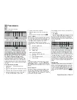
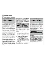
Curve MIX 9
0%
?
m
OU
T
P
U
T
--
+
1
100
–45%
10
8
Input
Curve
off
Point
Output
Setting reference points
When you move the transmitter control assigned to
the mixer input – in this case function 8 – a verti-
cal line in the graph follows the movement between
the two end-points. The current stick position is also
displayed in numerical form in the “Input” line. The
point at which this line coincides with the current cur-
ve is termed the “Output”, and this point can be va-
ried within the range -125% to +125% by setting the
reference points (see below). This control signal acts
upon the mixer output.
In the above example, the transmitter control for input
8 is at -45% travel, but the output signal is still 0%, as
no value has been entered at this juncture.
Between
the two end-points “L” and “H” and the de-
fault centre point (Point 1) it is possible to set a ma-
ximum of four reference points. However, if you fi rst
erase reference point “1” in the centre, you can set up
to six reference points; please note that the spacing
between adjacent reference points must be no less
Summary of Contents for mx-24s
Page 1: ...1...
Page 19: ...19 For your notes...
Page 35: ...35 For your notes...
Page 41: ...41 41 For your notes...
Page 57: ...57 For your notes...
Page 63: ...63 63 For your notes...
Page 69: ...69 69 For your notes...
Page 85: ...85 85 For your notes...
Page 99: ...99 For your notes...
Page 143: ...143 For your notes...
Page 191: ...191 For your notes...
Page 212: ...212 212 For your notes...
Page 213: ...213 213 For your notes...
Page 214: ...214 For your notes...
Page 216: ...216...


