background image

WWW.UNICORECOMM.COM

INSTALLATION AND OPERATION

USER MANUAL

Data subject to change without notice.

Copyright©  2009-2020, Unicore


Communications, Inc.


U

M220-INS

Positioning Module 

GNSS Integrated Navigation and 

Summary of Contents for UM220-INS NF

Page 1: ...W UNICORECOMM COM INSTALLATION AND OPERATION USER MANUAL Data subject to change without notice Copyright 2009 2020 Unicore Communications Inc UM220 INS Positioning Module GNSS Integrated Navigation an...

Page 2: ...mechanical including photocopying and recording for any purpose without the express written permission of the copyright owner Disclaimer The contents of this document are subject to revision without n...

Page 3: ...DIMENSIONS 8 4 4 PIN DEFINITION TOP VIEW 9 4 5 PCB PACKAGING 10 5 HARDWARE DESIGN 11 5 1 DESIGN IN CONSIDERATIONS 11 5 2 ANTENNA 12 5 3 SERIAL PORT 13 5 4 ODOMETER INSTALLATION 13 5 5 SYSTEM COORDINA...

Page 4: ...troduction 2 1 Product Description UM220 INS series products including UM220 INS NL UM220 INS NF are GNSS MEMS dual system modules designed for automotive navigation based on Unicore low power GNSS So...

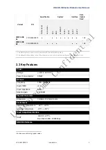
Page 5: ...NASS system 2 The default data update rate of the module is 1Hz which can be configured into 5Hz and 10Hz 2 2 Key Features Power Voltage 2 8V 3 6V VDC Power Consumption1 80mW RF Input Frequency 1559 1...

Page 6: ...BDS GPS GLO3 Tracking 161dBm 159dBm 161dBm 158dBm Acquisition 147dBm 144dBm 147dBm 142dBm Hot 154dBm 149dBm 154dBm 148dBm Reacquisition 157dBm 156dBm 157dBm 153dBm Data Update Rate 1Hz 5Hz 10Hz 1PPS...

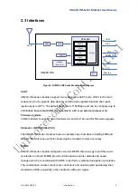
Page 7: ...s Ensure that COM1 is connected to a PC or an external processor for firmware upgrades COM2 is limited to support data transmission and can t be used for firmware upgrade Odometer FWD WHEELTICK The UM...

Page 8: ...n section 3 2 in the correct order Electrostatic discharge ESD may cause a damage to the device All operations mentioned in this chapter should be performed on an antistatic workbench using an antista...

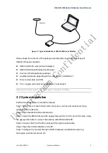
Page 9: ...s 7 and above Please keep the boxes and anti static plastic bags for storage and handling 3 2 System Installation Perform the steps below to install the module Step 1 Make sure to make full anti stati...

Page 10: ...D stress 2 KV HBM model 4 2 Operation Condition Item Pin Min Typical Value Max Uni t Condition Power Supply VCC Vcc 2 8 3 3 3 6 V Ripple Voltage Vp p 50 mV Peak current Iccp 52 mA Vcc 3 0 V Tracking a...

Page 11: ...chnical Specifications 8 4 3 Dimensions Symbol Min mm Type mm Max mm A 15 9 16 0 16 5 B 12 12 2 12 4 C 2 4 2 6 2 8 D 0 9 1 0 1 3 E 1 0 1 1 1 2 F 2 9 3 0 3 1 G 0 9 1 0 1 3 H 0 9 1 0 1 1 K 0 7 0 8 0 9 N...

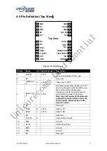
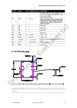
Page 12: ...n use 2 NC Reserved 3 TIMEPULS E O LVTTL Time pulse 1PPS 4 WHEELTIC K I LVTTL Odometer speed pulse bypass if not in use It is strongly recommended to use the maximum acceptable pulse frequency is 5KHz...

Page 13: ...oblems in the use of the product Please make sure the signal is correct 16 NC Reserved 17 NC Reserved 18 NC Reserved 19 NC Reserved 20 TXD1 O LVTTL UART 1 TX 21 RXD1 I LVTTL UART 1 RX 22 V_BCKP I 1 4V...

Page 14: ...nna and make sure the 50 impedance match on the circuit Ensure COM1 is connected to a PC or an external processor users can use this serial port to receive position data COM1 is also used for firmware...

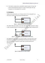
Page 15: ...VCC_RF Figure 5 1 UM220 INS Active Antenna 3V Solution If the UM220 INS series modules use an active antenna other than 3V the bias voltage V_BIAS required by the antenna is used to power the antenna...

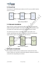
Page 16: ...ains effective direction and velocity pulse signals The odometer signal of vehicles is generally 12V and the signal quality is poor Therefore signal filtering optocoupler isolation and level conversio...

Page 17: ...tem 1 The normal direction of the shield is Z axis the long axis is Y and the short axis is X 2 The coordinate of the module must be consistent with the vehicle s which means X axis and R axis are par...

Page 18: ...or vibrations between the module and the vehicle UM220 INS series modules cannot be installed in the suspension part of the vehicle with elastic part When the vehicle is moving any change of the vehic...

Page 19: ...ch supports the free installation of the module with respect to any installation angle of the vehicle coordinate system such as the completely horizontal installation inclined installation at a certai...

Page 20: ...ion 2 Input the actual installation angles including angleR angleF and angleU into the module After the configuration is completed save the configuration to the flash through the CFGSAVE command other...

Page 21: ...l port or the sent MAP message is timeout 1 MAP information is received but not applied to the composite navigation 2 MAP information is received and applied to the composite navigation Fully Free Ins...

Page 22: ...tion quality is the faster the calibration will be It s required to make 90 degree turn maneuvers for more than five times while the vehicle is running normally Keep the forward driving speed above 36...

Page 23: ...d reel suitable for mainstream surface mount equipment packaged in vacuum sealed aluminum foil antistatic bags with a desiccant inside to prevent moisture When using reflow welding process to weld mod...

Page 24: ...between 20mm UM220 INS series modules are rated at MSL level 3 refer to the relevant IPC JEDEC standards for baking requirements Please access to the website www jedec org to download for details The...

Page 25: ...er to avoid device falling off the module should be placed on the top of the main board during welding Reflow soldering temperature curve is recommended as shown in figure 9 1 below M705 GRN360 is rec...

Page 26: ...www unicorecomm com Unicore Communications Inc www unicorecomm com Phone 86 10 69939800 Fax 86 10 69939888 info unicorecomm com 7 F3 No 7 Fengxian East Road Haidian Beijing P R China 100094...

Reviews: