181
181
Programming examples: Fixed-wing model
trol, INC / DEC button or three-position
switch).
FL
:
At this point you determine the extent to
which the aileron and fl ap servos are to
follow as fl aps when the selected transmit-
ter control (see above) or the three-positi-
on switch is moved.
Pressing
CLEAR
resets altered settings to the default
values.
Note:
We recommend that the mixer ratios should be set so
that the fl aps are positioned slightly “lower” than the
ailerons, as this helps to produce more effi cient lift
distribution across the wingspan.
Pressing the
HELP
button with the rotary control
pressed in takes you to the »
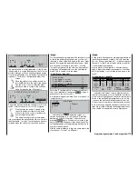
Servo display
«, whe-
re you can check the response of the AILE and FLAP
servos when you operate the selected fl ap control.
(First move the C1 stick to the forward position, as
this makes it easier to follow the “AILE” and “FLAP”
settings when you operate the associated transmitter
control.):
• In the centre position of the transmitter control, the
“FL.pos” setting in our example is +10% on AILE,
and +15% on FLAP.
• At the one end-point of the transmitter control
AILE and FLAP revert to their neutral positions, as
the mixer ratio in our example just compensates
for the FL.pos setting, whereas:
• AILE and FLAP move to the maximum defl ection
determined by the set mixer ratio at the opposite
end-point of the transmitter control.
Now we have to address the pitch-trim compensati-
on issue. To set the correct elevator travel we have
to leave the “Multi-fl ap” menu and return to the base
page of the »
Wing mixers
« menu:
«Thermal»
+5%
+5%
ASY
SYM
0%
=>
=>
2–>4
6–>3
Multi-flap menu
Brake settings
Aileron
Flaps
rudder
elevator
W I N G M I X E R S
At the two end-points of the three-position switch the
elevator (in our example) follows symmetrically, with
a mixer ratio of +5% (correct for each direction). On
the other hand, if you are using a proportional cont-
rol or one of the INC / DEC buttons, then the elevator
defl ects in proportion to the position of the transmit-
ter control.
The settings for the “Speed” fl ight phase can now be
adjusted in the same manner.
Notes:
• Regardless of these settings, the digital trims for
aileron, elevator and rudder take effect “globally”
or per “phase” according to your selected setting
in the »
Stick mode
« menu (see page 76).
• All values vary from model to model. You will need
to adjust the settings to suit your particular aircraft,
preferably during a test-fl ying programme.
Summary of Contents for mx-24s
Page 1: ...1...
Page 19: ...19 For your notes...
Page 35: ...35 For your notes...
Page 41: ...41 41 For your notes...
Page 57: ...57 For your notes...
Page 63: ...63 63 For your notes...
Page 69: ...69 69 For your notes...
Page 85: ...85 85 For your notes...
Page 99: ...99 For your notes...
Page 143: ...143 For your notes...
Page 191: ...191 For your notes...
Page 212: ...212 212 For your notes...
Page 213: ...213 213 For your notes...
Page 214: ...214 For your notes...
Page 216: ...216...

