176
Programming examples: Fixed-wing model
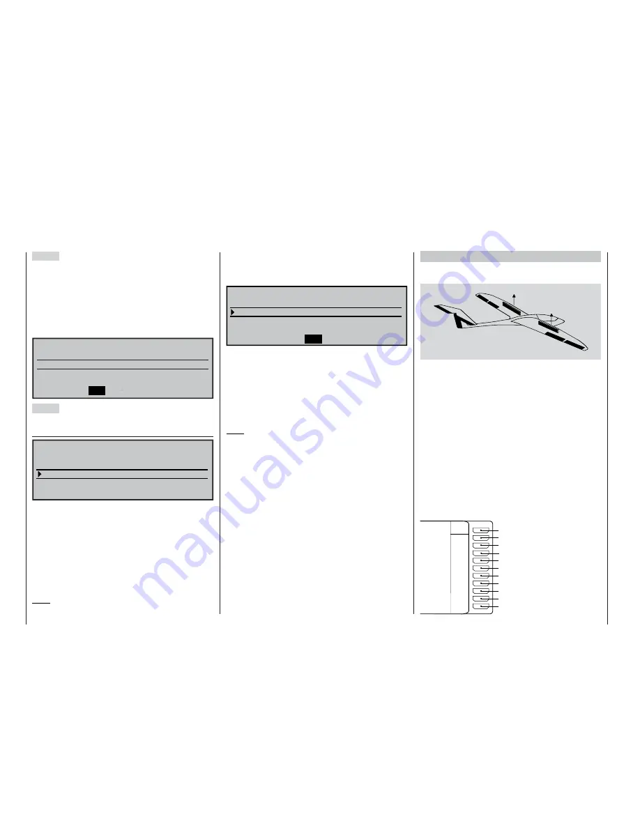
Step 5
It may be necessary to adjust the elevator trim for
each fl ight phase; this is carried out using the digital
trim lever for the elevator stick, and assumes that you
have set at least the elevator trim to “phase” (instead
of “global”) in the »
Stick mode
« menu, as recom-
mended at the start of this programming example.
Alternatively you can adjust the settings in the »
Pha-
se trim F3B
« menu:
Normal
Thermal
Speed
«Speed »
EL
0%
+10%
–8%
Step 6
In the menu …
»Wing mixers« (page 110)
«Speed »
33%
SEL
50%
=>
0%
0%
2–>4
3–>5
Brake settings
Aileron
Elevator
rudder
aileron
Aileron differential
W I N G M I X E R S
… the name of the currently active fl ight phase ap-
pears at the bottom of the screen. If you now move
the fl ight phase switch, the name of the phase selec-
ted by the switch appears, although the new phase
still contains the settings previously copied from the
“normal” fl ight phase. At this point you can enter the
phase-specifi c values for aileron differential, the ratio
for the aileron to rudder mixer and – if used – the ele-
vator to aileron mixer (the latter increases the model’s
agility around the lateral axis for aerobatics).
Note:
The displayed list of options varies according to the
Example 2
Glider with four-fl ap wing, two airbrakes and aero-
tow release
The following example assumes that you have alrea-
dy set up the model accurately in mechanical terms,
and have checked carefully that all the control sur-
faces move in the correct “sense” (direction) relative
to the stick commands. Please check these aspects
very carefully as described in the previous program-
ming examples, and carry out any changes or fi ne-tu-
ning required by swapping servos at the receiver and
/ or using the »
Servo adjustment
« menu.
Generally speaking, the fi ne-tuning of a model can
only be carried out in fl ight, and we therefore recom-
mend that you use one of the INC / DEC buttons
(CONTROL 5 or 6) for this purpose instead of the ro-
tary control; see page 28.
This programming example only works properly if the
servos are connected to the receiver output sockets
as shown in the diagram below:
AI
FL
FL
AI
EL
RU
Battery
Right airbrake
Right fl ap
Left fl ap
Right aileron
Rudder
Elevator
Left aileron
Left airbrake
Batt
9
8
7
6
5
4
3
2
1
10
Aero-tow release
Free, or auxiliary function
Receiv
er
number of servos entered in the “Ailerons / camber
fl aps” line of the »
Model type
« menu.
Finally switch to the “Brake settings” sub-menu …
AILE
–30%
+33%
=>
Crow
B R A K E S E T T I N G S
Elevat. curve
Diff. reduct.
… and enter in the “Crow” line the extent to which the
ailerons are to rise to act as airbrakes. In the “Diff. re-
duction” line you should enter the value which you
previously selected in the “Aileron differential” line, so
that the set differential is suppressed when the bra-
kes are deployed. In the “Elevat. curve” sub-menu you
may wish to set a corrective value for the elevator to
provide pitch trim compensation; see page 120.
Note:
The “Brake settings” menu is switched “off” if you en-
tered “Motor on C1 forward / back” in the »
Model
type
« menu (see page 70), and leave “yes” for the
currently active fl ight phase in the “Motor” column of
the »
Phase settings
« menu (see page 100). You may
therefore need to switch fl ight phases.
Summary of Contents for mx-24s
Page 1: ...1...
Page 19: ...19 For your notes...
Page 35: ...35 For your notes...
Page 41: ...41 41 For your notes...
Page 57: ...57 For your notes...
Page 63: ...63 63 For your notes...
Page 69: ...69 69 For your notes...
Page 85: ...85 85 For your notes...
Page 99: ...99 For your notes...
Page 143: ...143 For your notes...
Page 191: ...191 For your notes...
Page 212: ...212 212 For your notes...
Page 213: ...213 213 For your notes...
Page 214: ...214 For your notes...
Page 216: ...216...


