146
Fail-safe adjust
Fail-safe in the “PCM20” transmission mode
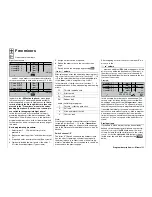
F A I L S A F E ( P C M 2 0 )
Time
hold
SEL
SEL
Battery F.S.
off
This menu appears in the multi-function list ONLY IF
YOU HAVE SELECTED THE PCM20 TRANSMISSI-
ON MODE. This mode of operation must be pre-set in
the »
Base setup model
« menu, which is model me-
mory specifi c. The PCM20 transmission mode can
be used with all receivers with “mc” in the designation
(mc-12, mc-18, mc-20, DS 20 mc, etc.).
Fail-safe programming for SPCM20 and APCM24 mo-
des will be discussed in the next section.
In this menu you can defi ne the behaviour of the re-
ceiver when a problem occurs in the radio link bet-
ween the transmitter and the receiver, and you can
also exploit the option of moving one servo to a parti-
cular position when the voltage of the receiver battery
falls below a certain value (“Battery Fail-Safe”).
Fail-safe and interference
The operational security of Pulse Code Modulati-
on (PCM) is inherently higher than that of simple Pul-
se Position Modulation (PPM), since the receiver in-
corporates an integral micro-processor which is ca-
pable of processing control signals even when picked
up in a “dirty” state. Only if the signals are incorrect
or garbled due to outside interference does the recei-
ver automatically replace the invalid signal with the
last received correct signal, which is stored in the re-
ceiver. This time-limited “hold-mode” procedure sup-
presses brief interference caused by local drops in
fi eld strength and similar momentary problems, which
otherwise result in the familiar “glitches”.
Caution:
We strongly recommend that you exploit the safe-
Program description:
Special functions
ty potential inherent in the use of the PCM trans-
mission modes PCM, SPCM and APCM by at least
setting the throttle to move to idle (glow motor)
or the motor to stop completely (electric motor) if
Fail-Safe is triggered. If interference should occur
with these settings, it is much less likely that the
model will wreak havoc and cause personal injury
or property damage if the model is on the ground.
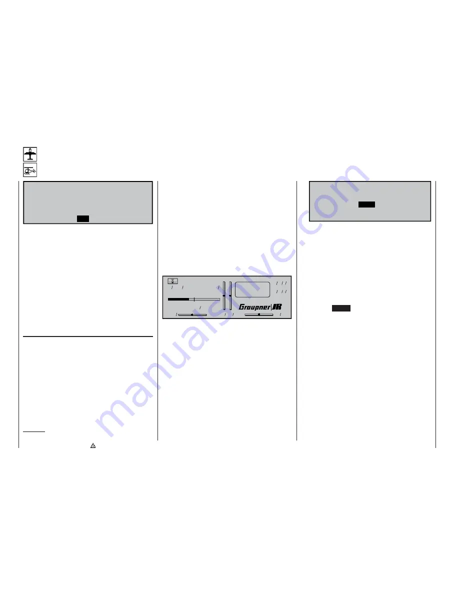
If you have selected a PCM transmission mode for
the current model memory but have not yet carried
out the fail-safe programming, you will see a warning
message on the screen when you switch the transmit-
ter on. The message remains on-screen in the basic
display for a few seconds:
Model name
#01 0:35h
PCM20
H-J.Sandbrunner
9.5V
2:50h C62
0
0
0
0
S
F
0 00
0 00
:
:
F a i l S a f e
s e t u p
t . b . d .
If a longer period of interference affects the radio link
between the transmitter and receiver, the PCM20
operating mode offers two optional types of “FAIL-
SAFE” programming; you can select your preferred
one using the left-hand
SEL
fi eld:
1. “Hold” mode
If you confi rm the left-hand
SEL
fi eld with a brief
press on the rotary control, and set “hold” in the
highlighted fi eld, when interference strikes, the
servos stay continuously at the position corres-
ponding to the last valid signal until the receiver
picks up another signal which it recognises as va-
lid.
2. Variable FAIL-SAFE programming with overwri-
te (display: “.25s, 0.5s or 1.0s”)
If you set a pre-selected time instead of “hold”
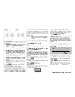
mode, the display initially changes as follows:
. 2 5 s
SEL
SEL
STO
F A I L S A F E ( P C M 2 0 )
Time
Battery F.S.
off
Position
With this arrangement, “hold” mode is effective
when interference initially strikes, but after the set
delay has elapsed the servos move to previously
determined positions until the receiver again picks
up a valid control signal. As soon as the recei-
ver detects valid signals again, the “hold” phase or
Fail-Safe servo positions are instantly abandoned.
The delay time, i. e. the time from the onset of in-
terference to the triggering of FAIL-SAFE mode,
can be set to any of three values: 0.25 sec., 0.5
sec. and 1.0 sec. These variations are designed to
cater for differing operational conditions.
Pressing
CLEAR
resets the Fail-Safe setting in
the highlighted fi eld to “hold”.
Setting the servo positions
The FAIL-SAFE servo positions are freely pro-
grammable for the receiver outputs 1 … 8.
Use the rotary control to select the
STO
fi eld, then
move the servos 1 … 8 to the appropriate po-
sitions using the transmitter controls, and brief-
ly press the rotary control to store the positions
as the “Fail-Safe” settings. This data is transmit-
ted to the receiver at regular intervals, so that the
receiver can always revert to them if interference
should strike.
When you store the data by giving the rotary con-
trol a brief press, you will see the following brief
message on the screen:
Summary of Contents for mx-24s
Page 1: ...1...
Page 19: ...19 For your notes...
Page 35: ...35 For your notes...
Page 41: ...41 41 For your notes...
Page 57: ...57 For your notes...
Page 63: ...63 63 For your notes...
Page 69: ...69 69 For your notes...
Page 85: ...85 85 For your notes...
Page 99: ...99 For your notes...
Page 143: ...143 For your notes...
Page 191: ...191 For your notes...
Page 212: ...212 212 For your notes...
Page 213: ...213 213 For your notes...
Page 214: ...214 For your notes...
Page 216: ...216...


