47
47
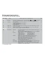
Brief programming instructions
time:
symmetrical or asymmetrical reduction of speed of transmitter control travel. Adjustment range: 0 …
9.9, e. g. for scale sequences, delayed motor acceleration etc..
•
Stick mode
Trim:
“global”:
the trims for roll, pitch-axis and tail rotor affect all fl ight phases (trim symbol in the basic
display shows “shadow”).
“phase”:
the trims for roll, pitch-axis and tail rotor can be set to operate separately for each fl ight
phase (trim symbol in the basic display shows no “shadow”).
“Thr lim”:
the collective pitch / throttle trim is controlled by the throttle limiter.
“Thr AR”:
the collective pitch / throttle trim takes effect in the Auto-rotation phase.
Tr.step:
adjustment of the increment (step) size for all four digital trim levers, range 1 to 10 (standard = 4).
time:
symmetrical or asymmetrical reduction of transmitter control transit speed. Available range: 0 ... 9.9
sec., e. g. for scale processes, “soft” motor acceleration etc..
77
•
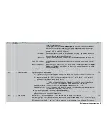
Control adjust
Assignment and de-coupling (display = “free”) of transmitter controls (INC / DEC buttons “CONTROL 5 + 6”, 3-po-
sition switches “CONTROL 7 + 8” and side-mounted proportional controls “Controls 9 + 10”), switches SW 1 … 4,
7 and 8, plus optionally also the C1 stick. Inputs 5 … 8 are programmable separately for each fl ight phase, but in-
puts 9 … 12 only once in each model memory.
offset:
the centre point of the transmitter control can be offset within the range -125% to +125%.
travel:
variable control travel, symmetrical or asymmetrical between -125% and +125%; direction of control’s
effect can also be reversed.
time:
symmetrical or asymmetrical reduction of transmitter control transit speed. Available range: 0 ... 9.9 sec.,
e. g. for scale processes, “soft” motor acceleration etc..
78
•
Control adjust
Assignment and de-coupling (display = “free”) of transmitter controls (INC / DEC buttons “CONTROL 5 + 6”, 3-po-
sition switches “CONTROL 7 + 8” and side-mounted proportional controls “Controls 9 + 10”), switches SW 1 … 4,
7 and 8, plus optionally also the C1 stick. Inputs 5 … 8 are programmable separately for each fl ight phase, but in-
puts 9 … 12 only once in each model memory.
Note:
Input 12 is reserved for the “throttle limit” function. The assigned transmitter control only operates the throttle ser-
vo in addition to servo 12. For this reason servo 12 can only be accessed via a mixer using the »
Mix-only chan-
nel
« function. Application of “throttle limit”: see page 82. Transmitter control 9 (the right-hand proportional control)
is assigned to this in the software.
offset:
the centre point of the transmitter control can be offset within the range -125% to +125%.
travel:
variable control travel, symmetrical or asymmetrical between -125% and +125%; direction of control’s
effect can also be reversed.
time:
symmetrical or asymmetrical reduction of transmitter control transit speed. Available range: 0 ... 9.9 sec.,
e. g. for scale processes, “soft” motor acceleration etc..
80
Display
Menu
Brief description of menu and operating notes
Page
Summary of Contents for mx-24s
Page 1: ...1...
Page 19: ...19 For your notes...
Page 35: ...35 For your notes...
Page 41: ...41 41 For your notes...
Page 57: ...57 For your notes...
Page 63: ...63 63 For your notes...
Page 69: ...69 69 For your notes...
Page 85: ...85 85 For your notes...
Page 99: ...99 For your notes...
Page 143: ...143 For your notes...
Page 191: ...191 For your notes...
Page 212: ...212 212 For your notes...
Page 213: ...213 213 For your notes...
Page 214: ...214 For your notes...
Page 216: ...216...


