202
»Control adjust« (page 80)
+100%
«Normal »
ASY
SYM
ASY
SYM
0%
+100%
0.0 0.0
Cnt. 5
0%
0%
+100%+100%
+100%
+100%+100%
0.0 0.0
0.0 0.0
0.0 0.0
SEL
0%
+50%
SEL
–time+
Throt
Gyro
Input
free
free
free
7
Input
6
offset
–
8
5
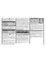
Requirement:
The governor must be programmed in such a way
that the “back” position of the three-position switch,
e. g. CONTROL 8, equates to “governor off”, while
the forward position determines the actual rotational
speed of the rotor.
In Phase 1 “Normal” the speed governor should be
kept switched off; this phase is used primarily for che-
cking the motor and other general settings.
You can accomplish this by selecting the “Input 8” line
using the rotary control: leave or reset this to “free”,
then simply change the value to -100% (max. -125%)
in the “offset” column.
+100%
ASY
SYM
ASY
SYM
0%
+100%
0.0 0.0
0%
–125%
+100%+100%
+100%
+100%+100%
0.0 0.0
0.0 0.0
0.0 0.0
SEL
0%
+50%
SEL
«Normal »
Cnt. 5
offset
–time+
Throt
Gyro
Input
free
free
7
Input
6
–
8
5
free
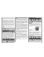
Call up the »
Servo display
« menu, and check that
the indicated “servo travel” of channel 8 stays fi xed at
-100% (or up to -125%). This means that the speed
Suggestion for expanded programming: speed
governor
At some stage you will probably consider equipping
your model helicopter with a speed regulator, or go-
vernor, i. e. a device such as the mc Heli Control. This
unit provides a safe way of fl ying your helicopter with
different system rotational speeds. It is sensible to
couple the individual rotational speeds with the fl ight
phases, so that you can make additional adjustments
as required for each rotor speed.
Before you carry out the programming at the trans-
mitter, it is essential to install the speed governor and
program it exactly as described in the manufacturer’s
instructions. As you would expect, the
mx
-24s of-
fers several possible methods of implementing diffe-
rent rotational speeds in individual fl ight phases. The-
se include “ultra-convenient” facilities, but they do call
for much greater programming effort at the transmit-
ter, and for this reason are best reserved for the ex-
perienced pilot.
The following example involves certain restrictions
in terms of convenience, but the effi ciency of rotor
speed governing is perfectly adequate, and the sys-
tem is reasonably easy to program and – not least –
straightforward to operate.
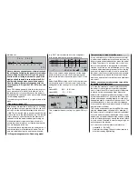
The procedure is similar to that for setting up gyro
gain. As in that case, the adjustment facilities of “-tra-
vel+” and “offset” in the »
Transmitter control ad-
just
« menu are exploited in order to defi ne the end-
points of a three-position switch (SW 5 + 6 or 9 + 10
or CONTROL 7 + 8). It is equally possible to use one
of the INC / DEC buttons or one of the side-mounted
proportional controls.
To set up this system you should again call up the
menu:
0
100
125
%
+100%
-100%
0
-100
-125
OUTPUT
Control travel
Since the switch
has three posi-
tions, only three settings are
available for the transmitter
control travel.
202
Programming examples: Model helicopter
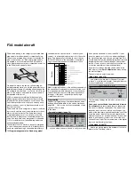
nor (regulator) programmed as described in the sec-
tion starting in the next column, a sequence of the
type “normal / hover / aerobat” might well be approp-
riate.
The model settings which you entered before you as-
signed a phase switch are now located in the “nor-
mal” fl ight phase. Now that you have assigned multip-
le fl ight phases, this is the phase which is called up
when the phase switch is at the centre position.
These settings are known to be correct, i. e. you have
test-fl own the model using them, so it is a good star-
ting point to copy them into the other fl ight phases,
as this ensures that at least the model fl ies safely in
each phase.
This is done using the »
Copy / Erase
« menu; see
page 60 :
=>
=>
=>
=>
=>
=>
Erase model
Copy model –>
model
Copy MX24 –>
external
Copy external –> MX24
Copy flight phase
Back-up all models –>
PC
Once you have set up a series of fl ight phases it is
possible to make changes to the phase-specifi c me-
nus for each phase separately. Since the
mx
-24s
features digital trims, in the Helicopter program all
four trim positions are stored separately for each fl ight
phase, in addition to the other menu settings which
you have entered separately for each fl ight phase;
see the »
Stick mode
« menu, page 77.
0.0s 0.0s
0.0s 0.0s
0.0s 0.0s
SYM ASY
SEL
global
Phase
global
4
4
4
4
0.0s 0.0s
SEL
– time +
Pitch/thr
Roll
Pitch ax.
Tail rot.
Tr.step
Thr Lim
Trim
Forward
switch end-
point
Switch cen-
tre position
Back switch
end-point
Summary of Contents for mx-24s
Page 1: ...1...
Page 19: ...19 For your notes...
Page 35: ...35 For your notes...
Page 41: ...41 41 For your notes...
Page 57: ...57 For your notes...
Page 63: ...63 63 For your notes...
Page 69: ...69 69 For your notes...
Page 85: ...85 85 For your notes...
Page 99: ...99 For your notes...
Page 143: ...143 For your notes...
Page 191: ...191 For your notes...
Page 212: ...212 212 For your notes...
Page 213: ...213 213 For your notes...
Page 214: ...214 For your notes...
Page 216: ...216...


