51
51
Brief programming instructions
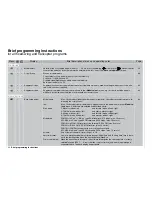
In the basic setting all switches always generate “Phase 1”; the same applies to non-assigned switch combinati-
ons.
The switches assigned under “A” and “B” have special priorities:
Switch “A” in the ON position the fl ight phase assigned to this switch always has priority over all other fl ight pha-
ses (= fl ight phases for switch positions “B” to “F”).
Switch “B” in the ON position with the exception of the priority assigned under “A”, the associated fl ight phase
has priority over all other fl ight phases assigned to switches “C” to “F”.
Caution:
Model helicopters: the auto-rotation phase always has absolute priority over all assignments “A” … “F”
set up in this menu.
•
Phase trim F3B
Depending on the model type selected in the »
Model type
« menu (see page 70), a minimum of one control sur-
face function (
EL
) and a maximum of four control surfaces (
EL
,
AIL
,
FL
,
FL2
) are available for phase-specifi c trim
settings.
105
•
•
Non-delayed chan
The delay when a new fl ight phase is selected can be switched off for individual channels, separately for each
fl ight phase. Examples: motor OFF with electric models, activating and disabling heading lock with gyro systems.
105
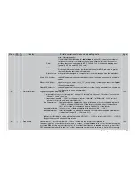
Timers
Timers
•
•
Timers (general)
“Model time”:
reset with a brief press on the rotary control with the
CLR
fi eld active (timer switchable).
“Batt. time”:
automatic reset when battery is recharged; can also be reset by pressing
CLR
.
“Top / Centr”: various names can be assigned to these two timers. If you select “Stopwatch” and “Motor time”,
the timer continues to run as long as the switch assigned on the right of the screen is set to ON. If
you assign the names “Flight time” and “Slot time”, the timer is started by operating an assigned
switch (preferably the momentary switch SW8) and stopped by pressing the
ESC
button or
ESC
with the rotary control held pressed in.
CLEAR
resets all previously stopped timers in the basic
display to the appropriate starting value.
“Timer” column: preset 0:00 means a count-up timer; time preset via rotary control (maximum 180 min 59 sec) ge-
nerates a count-down timer (fl ashing colon in the basic display); the recorded time is highlighted
after “zero”.
“Alarm” column: timing and sequence of warning beeps when the alarm timer approaches and passes through
zero (max. 90 sec.).
106
•
•
Fl. phase timers
An additional fl ight phase specifi c timer is superimposed on the screen in place of the
GRAUPNER/JR
logo. This
timer is assigned in the »
Phase settings
« menu. These “fl ight phase timers” are controlled using the On / Off
switch assigned in this menu. A previously stopped timer is reset to the starting value from the basic display by
pressing
CLEAR
.
108
Display
Menu
Brief description of menu and operating notes
Page
Summary of Contents for mx-24s
Page 1: ...1...
Page 19: ...19 For your notes...
Page 35: ...35 For your notes...
Page 41: ...41 41 For your notes...
Page 57: ...57 For your notes...
Page 63: ...63 63 For your notes...
Page 69: ...69 69 For your notes...
Page 85: ...85 85 For your notes...
Page 99: ...99 For your notes...
Page 143: ...143 For your notes...
Page 191: ...191 For your notes...
Page 212: ...212 212 For your notes...
Page 213: ...213 213 For your notes...
Page 214: ...214 For your notes...
Page 216: ...216...

