194
Programming examples: Fixed-wing model
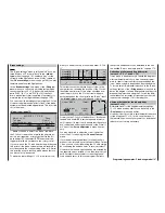
trimmed out.
Pos
hold
1
2
3
4
5
6
7
8
STO
F A I L S A F E
Never, under any circumstances, attempt to check
the settings by switching the transmitter off when
you are fl ying a model aircraft! If you do, you run
a serious risk of losing the model, as you will be
highly unlikely to be able to re-activate the RF si-
gnal quickly enough when you switch on again,
since the transmitter always responds with the
security query “RF signal on YES / NO” when swit-
ched on.
Since F3A models generally have two aileron servos,
it has proved useful to defl ect both ailerons “up” for
the landing. In most cases this causes the model to
fl y slightly more slowly and with a
more stable attitude
on the landing approach.
To achieve this you will need to program mixers in the
menu ...
»Free mixers« (page 135)
Both ailerons are required to defl ect “up” as a landing
aid, in parallel with the movement of the throttle stick,
but only from the half-throttle setting in the direction
of idle. The further the stick is moved towards the idle
position, the more the ailerons defl ect up. The reverse
occurs when you open the throttle: the ailerons are
centred to avoid the model suddenly ballooning up.
A little down-elevator must usually be mixed in to
ensure that the aircraft does not climb when the aile-
rons are deployed in this way.
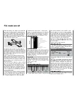
To meet both these requirements you need the two li-
near mixers shown in the illustration below. The mi-
xers are activated using one and the same switch,
e. g. SW 7, which therefore has to be assigned to
both mixers with the same switching direction.
5
=>
EL
??
??
- - - -
??
??
- - - -
SEL SEL
SEL
C1
C1
7I
7I
=>
1
2
3
4
LinearMIX
type
LinearMIX
LinearMIX
LinearMIX
from
to
Adjust
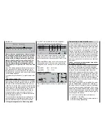
Move to the second screen page and set the appro-
priate mixer ratios. In both cases the mixer neutral
point should be left at the centre point of the C1 stick
arc.
Select the
ASY
fi eld, then set 0% for both mixers abo-
ve the centre point of the control, and the following
settings below the centre point, i.e. in the direction of
idle:
LinearMIX 1:
-60% ... -80% and
LinearMIX 2:
-5% ... -10% .
Example of LinearMIX 1:
0%
0%
m
OU
T
P
U
T
--
+
100
STO
ASY
SYM
CLR
C1
5
Offset
–70%
Linear MIX 1
Mix input
This completes the basic set-up for a typical F3A mo-
del.
Compensating for model-specifi c errors
It is an unfortunate fact of life that even very careful-
ly built models exhibit minute faults and inaccuracies
which produce unwanted deviations when the model
is fl ying. The mixers of a computer radio control sys-
tem are then required to compensate for these defi -
ciencies. In this section we will describe how to carry
out these adjustments, but please note the following
points before we get started: it is vital to ensure that
the model is built as accurately as humanly possible,
is balanced perfectly around the lateral and longitu-
dinal axes, and that motor downthrust and side thrust
are correct.
Rudder causes unwanted movement around the
longitudinal and lateral axes
It is often the case that a rudder command causes
the model to rotate slightly around the longitudinal
and / or lateral axes. This is particularly troublesome
in what is known as knife-edge fl ight, where the
model’s total lift is generated by the fuselage, aided
by the rudder defl ection. The result is that the model
rotates and changes heading slightly, as if the pilot
had applied aileron or elevator at the same time. The-
se tendencies have to be corrected with compensa-
tion around the lateral axis (elevator) and around the
longitudinal axis (aileron).
This can be achieved easily with the
mx
-24s, explo-
iting the »
free mixers
« once again. For example, if
the model rotates to the right around the longitudinal
(roll) axis when the rudder is defl ected, then a mixer
needs to be set up which defl ects the ailerons slightly
to the left. Heading changes around the lateral (eleva-
tor) axis can be corrected in a similar way using a mi-
xer acting upon the elevator:
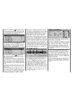
a) Correction around the lateral axis (elevator)
LinearMIX
3:
“RU
EL”
Asymmetrical setting. The exact values required
must be found by fl ight testing.
Summary of Contents for mx-24s
Page 1: ...1...
Page 19: ...19 For your notes...
Page 35: ...35 For your notes...
Page 41: ...41 41 For your notes...
Page 57: ...57 For your notes...
Page 63: ...63 63 For your notes...
Page 69: ...69 69 For your notes...
Page 85: ...85 85 For your notes...
Page 99: ...99 For your notes...
Page 143: ...143 For your notes...
Page 191: ...191 For your notes...
Page 212: ...212 212 For your notes...
Page 213: ...213 213 For your notes...
Page 214: ...214 For your notes...
Page 216: ...216...


