111
Program description:
Mixers
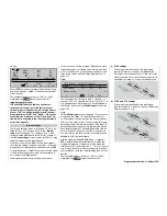
Basic programming procedure:
1. Hold the rotary control pressed in, and select the
mixer line.
Depending on the mixer, the bottom line of the
screen now displays either the symbol for “next
page” (
), or
SEL
or
SYM
and
ASY
(for setting
mixer ratios separately for each side of centre), as
well as
.
2. Select one of these fi elds using the rotary control.
3. Press the rotary control briefl y.
Depending on the line you have selected, you will
now either move to the next page, where the pro-
cedure is the same, or the highlighted fi eld will
move to the selected line in which you can set the
desired values.
4. Use the rotary control to set the degree of differen-
tial or the mixer ratio, or assign the switch.
Either negative or positive parameter values can
be set; this allows you to reverse the direction of
servo rotation if necessary, i. e. if one of the cont-
rol surfaces operates in the wrong “sense”.
(Pressing
CLEAR
= resets to default value.)
5. Press the rotary control briefl y to leave the menu.
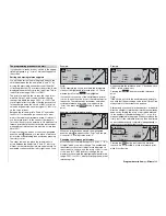
Assigning switches
As an option, the wing mixers “Aileron 2
4 rudder”,
“Elevator 3
6 fl ap” and “Flap 6
3 elevator” can
be assigned a switch or an expanded switch, so that
they can be turned on and off in fl ight. If you call up
this line you will see the (by now) familiar switch sym-
bol
.
Transition delay
The delay time, or transition time, which is set in the
»
Phase assignment
« menu (see page 104) separa-
tely for each fl ight phase, is designed to avoid abrupt
changes of wing fl ap settings when you switch bet-
ween the fl ight phases.
Mixer neutral point (offset)
By default the neutral point (“offset”) of all the mixers
in the “Brake settings” sub-menu is the position of the
transmitter control at which the airbrakes are retrac-
ted.
The input (1, 7, 8 or 9) and the offset are determined
in the “Brake” line of the »
Model type
« menu; see
page 70. If you select “Input 1”, please note that you
should fi rst enter your preferred “Throttle min.” posi-
tion as “forward / back” in the “Motor” line before you
determine the offset point.
Note:
If the offset is not positioned right at the end of the
travel of the transmitter control, then the remainder of
the travel is a “dead zone”, i. e. the transmitter control
no longer has any infl uence on any of the mixers in
the “Brake settings” sub-menu. The mixer travel is au-
tomatically expanded back to 100%.
The neutral point of all other mixers in the »
Wing mi-
xers
« menu is at the zero position of the transmitter
control (control centre), i. e. they have no effect at that
point. At full travel the set value is mixed in.
Mixer functions
The following section discusses the individual opti-
ons offered by the »
Wing mixers
« menu, separately
for models with one, two and multiple wing fl aps. Ho-
wever, we preface this with a few notes on differential
travel for ailerons and fl aps.
Aileron differential
For aerodynamic reasons, the drag generated by the
down-going aileron is greater than that produced by
the up-going aileron when an aileron command is gi-
ven. This differential drag causes a yawing motion
around the vertical axis, in the opposite direction to
the desired turn. That is why this effect is also known
as “adverse yaw”. Power models generally have re-
latively short moment arms which negate this effect,
but it is much more pronounced in model gliders with
high aspect ratio wings, and usually has to be coun-
tered by giving a simultaneous rudder defl ection in
the opposite direction to the yaw. However, this in
turns causes additional drag and therefore lowers the
aircraft’s effi ciency.
Electronic differential aileron travel is one answer, but
it can only be used if a separate servo is installed for
each aileron. Aileron differential reduces the angu-
lar travel of the down-going aileron relative to that of
the up-going aileron, and this reduces aileron drag
and therefore the adverse yaw. The aileron servos are
usually installed directly in the wings for this purpose;
this arrangement produces shorter mechanical lin-
kages, which in turn help to reduce slop, and should
ensure reliable, reproducible aileron travels.
Mechanical solutions are also possible, but they usu-
ally have to be “designed in” when the model is built,
and in any case signifi cant mechanical differential
tends to create additional slop in the control system.
Electronic differential offers several important advan-
tages.
For example, the degree of differential can be adjus-
ted at any time without affecting the travel of the up-
going aileron. In the extreme case it is possible to
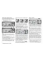
0% (Normal)
50% (Differential)
100% (Split)
Summary of Contents for mx-24s
Page 1: ...1...
Page 19: ...19 For your notes...
Page 35: ...35 For your notes...
Page 41: ...41 41 For your notes...
Page 57: ...57 For your notes...
Page 63: ...63 63 For your notes...
Page 69: ...69 69 For your notes...
Page 85: ...85 85 For your notes...
Page 99: ...99 For your notes...
Page 143: ...143 For your notes...
Page 191: ...191 For your notes...
Page 212: ...212 212 For your notes...
Page 213: ...213 213 For your notes...
Page 214: ...214 For your notes...
Page 216: ...216...


