122
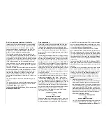
Program description:
Mixers
Helicopter mixer
Mixers variable separately in fl ight phases
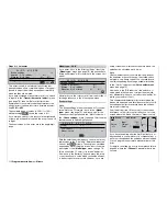
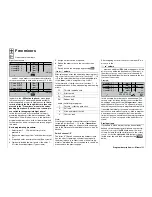
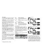
This menu describes all the helicopter mixers which
can be varied separately in each fl ight phase, with
the exception of the mixers for the auto-rotation fl ight
phase, which are covered in detail in the section star-
ting on page 132. These mixers are used for the basic
set-up of a model helicopter.
For details of fl ight phase programming please refer
to the following menus:
•
»Base setup model«
, page
66
•
»Phase settings«
, page
102
•
»Phase assignment«
, page
104
Whenever fl ight phases have been assigned, the acti-
ve fl ight phase is displayed at the bottom edge of the
screen, e. g. “normal”.
In each of these fl ight phases – with the exception of
the Auto-rotation phase – the typical helicopter mixing
and coupling functions shown in the screen-shot abo-
ve are available for setting up the model helicopter.
These functions are described in the fi rst part of this
comprehensive chapter.
General information on mixers
(see also pages 110 and 134).
An arrow “
” indicates a mixer. The signal which
fl ows directly from a transmitter stick to the associa-
ted servo is “bled off” at a particular point, and the de-
rived signal is then processed in such a way that it af-
fects another control channel, and eventually another
receiver output. For example, if you set up a “Pitch-
axis
tail rotor” mixer, the result is that the tail rotor
servo follows the movement of the pitch-axis control
system when you operate the pitch-axis stick.
Eight-point curves are available for the collective
pitch curve in all fl ight phases, and for the two mi-
xers “Channel 1
throttle” and “Channel 1
tail ro-
tor”. This means that you can program a non-linear
response curve along the travel of the corresponding
stick; see also the «
Channel 1 curve
« menu, page
92.
A brief press on the rotary control or the
ENTER
but-
ton takes you to the screen page for setting an eight-
point curve; see below. The curve is set up basically
in the same way as the Channel 1 curve for helicop-
ters, but we will describe it again here in detail to save
you having to leaf through the manual.
In the remaining lines you can activate the
SEL
fi eld
and use the rotary control in the highlighted fi eld to
enter a mixer value. Pressing
CLEAR
resets the pa-
rameter value to 0%. These mixers are used for the
basic set-up procedure of your model helicopter.
The basic programming procedure:
1. Select the mixer with the rotary control pressed in.
The bottom line of the screen now shows
SEL
or
an arrow
.
2. A brief press on the rotary control with the
SEL
fi eld highlighted allows you to set the mixer ratios
directly: set the mixer value using the rotary con-
trol. Otherwise you will need to switch to the se-
cond screen page where you can set up the ap-
propriate curve mixer. (
CLEAR
= 0%).
3. A second brief press on the rotary control conclu-
des the input process.
4. Press
ESC
to move back.
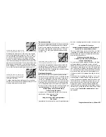
Pitch
A brief press on the rotary control or the
ENTER
but-
ton switches to the second screen page:
Pitch
-60%
?
m
OU
T
P
U
T
--
+
1
100
«normal »
-60%
Input
Curve
off
Point
Output
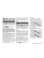
The »
Channel 1 curve
« menu affects all servos
which are infl uenced by the throttle / collective pitch
stick, but this display refers only to the control curve
of the collective pitch servos.
Note:
The output signal of the »Channel 1 curve« acts
as an input signal for the collective pitch curve
which you program at this point: the vertical line
in the diagram, which moves in parallel with the
throttle / collective pitch stick, refl ects the actual
Channel 1 curve.
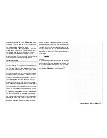
The control curve can be defi ned by up to eight
points, termed “reference points” in the following sec-
tion; they can be placed at any point along the stick
travel. The curve can be set up separately for each
fl ight phase.
Initially, however, fewer reference points are adequa-
te for setting up the collective pitch curve. As a basic
rule we recommend that you start with just the three
standard reference points, which are already pre-set
in the basic software set-up. These three points de-
fi ne a linear “curve” as the base setting: namely the
two end-points at the bottom end of the control travel
“L” (low = -100% travel) and the top end of the control
travel “H” (high = +100% travel), together with point
“1”, which is exactly in the centre of the control travel.
Pitch
Channel 1
Channel 1
Pitch ax.
0%
Gyro suppression
Swashplate rotation
«normal »
=>
=>
=>
0%
0%
0%
0%
0%
0°
Swashplate limiter
off
Throttle
Tail rot.
Tail rot.
Throttle
Throttle
Roll
Roll
Tail rot.
Throttle
Pitch ax.
Tail rot.
Summary of Contents for mx-24s
Page 1: ...1...
Page 19: ...19 For your notes...
Page 35: ...35 For your notes...
Page 41: ...41 41 For your notes...
Page 57: ...57 For your notes...
Page 63: ...63 63 For your notes...
Page 69: ...69 69 For your notes...
Page 85: ...85 85 For your notes...
Page 99: ...99 For your notes...
Page 143: ...143 For your notes...
Page 191: ...191 For your notes...
Page 212: ...212 212 For your notes...
Page 213: ...213 213 For your notes...
Page 214: ...214 For your notes...
Page 216: ...216...


