162
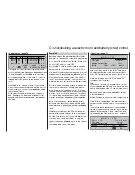
»Servo adjustment« (page 74)
Servo 1
=>
0% 100% 100% 150% 150%
Servo 2 =>
0% 100% 100%
150% 150%
Servo 3 =>
0% 100% 100%
150% 150%
Servo 4 =>
0% 100% 100%
150% 150%
Rev
SEL
SYM ASY
SYM ASY
cent. – travel
+
– limit +
SEL
In this menu you can set various parameters rela-
ting to the servos, i. e. “
Direction of rotation
” “
Neu-
tral setting
”, “
Servo travel
” and “
Travel limit
” (maxi-
mum permitted servo travel) to suit the requirements
of the model.
By “requirements” we mean adjustments to servo
centre and servo travel which are needed to compen-
sate for
minor
manufacturing tolerances in servos and
slight inaccuracies in the model itself.
Notes:
• For mechanical and electronic reasons, the maxi-
mum possible travel of all GRAUPNER servos is
150% each side of centre. If you exceed this va-
lue, for example by the sum of the values in the
two columns “Centre” and “Servo travel”, then the
associated servo will no longer follow control com-
mands beyond this point. Bear in mind also that
mixers and settings in the »
Dual Rate / Expo
«
menu also affect servo travels.
• The facilities provided in this menu for selecting
asymmetrical servo travels are NOT intended for
setting differential travel on ailerons and / or cam-
ber-changing fl aps. There are functions designed
specifi cally for this in the »
Wing mixers
« menu;
for a V-tail the »
Dual mixers
« menu should be
used. In the latter case it is ESSENTIAL to set the
tail type to “normal” in the »
Model type
« menu
(see page 70).
In the last column – “
Travel limit
” – the basic settings
of 150% in each case can and should be reduced sig-
nifi cantly, since the values stated here act virtually as
“limiters”. This setting defi nes the point on the servo’s
travel beyond which it is not permitted to move, and is
designed to prevent the servo striking its mechanical
end-stops and stalling (drawing a heavy current). The
deciding factor for this value is therefore the end of
the mechanical movement available at the servo, con-
trol surface and / or linkage.
As an example of this we will consider a model with
a standard (cruciform) tail in which the rudder moves
in a wedge-shaped cut-out in the elevator. The rud-
der must not defl ect to the point where it fouls the ele-
vator and perhaps jams it, and to avoid this it is usual
practice to adjust the pushrod travel mechanically so
that at full stick defl ection the rudder has slight clea-
rance to the elevator. Provided that the rudder is con-
trolled solely by the rudder stick, this system presents
no further problems. However, if you set up a mixer
which also affects the rudder, i. e. you add a supple-
mentary signal to the normal rudder signal (e. g. an
“Aileron 2
4 rudder” mixer), the cumulative effect
of the two signals may be excessive, and the rudder
may still foul the elevator. Setting the travel limit cor-
rectly in this menu will reliably prevent the rudder de-
fl ecting too far. However, take care not to set the tra-
vel limit at too low a value, as this would place an ex-
cessive restriction on the rudder defl ection.
Alternatively, of course, you could reduce the travels
on both sides, so that neither control surface fouls the
other even when the maximum cumulative defl ections
are applied. However, with this method you would
have to accept a permanent reduction in the normal
rudder travel in order to prevent an event which might
only occur very rarely.
The following menu is also of interest, and not only for
power fl iers:
»Stick mode« (page 76)
Channel 1
Aileron
0.0s 0.0s
Elevator
0.0s 0.0s
Rudder
0.0s 0.0s
Tr.step
SYM ASY
SEL
global
global
global
global
Trim
4
4
4
4
0.0s 0.0s
– time +
The increment adjustment for the digital trims in the
“Tr.step” column (number of trim increments for each
“trim lever click”) is of general interest, and can be set
separately for each of the four trim levers. Later, when
you are programming fl ight phases, the second co-
lumn of this menu allows you to select whether the
trims for aileron, elevator and rudder are to act “glo-
bally”, i. e. are applicable to all fl ight phases regard-
less, or are to act differently according to the fl ight
phase selected.
The “time” column, in contrast, is of no interest to us
at this early stage of programming.
When you have completed the settings to this point,
a fi xed-wing model, either powered or glider, is rea-
dy to fl y in its basic form. However, there are no “refi -
nements” in this set-up, and it is precisely the refi ne-
ments which will give you more long-term pleasure in
your fl ying. Assuming that you are already capable of
fl ying your model safely, it is time to get a taste of the-
se extra facilities; to this end we now move on to the
menu ...
»Wing mixers« (page 110)
«normal »
+ 30%
SEL
+ 50%
2–>4
3–>5
=>
0%
0%
Brake settings
Aileron
Elevator
rudder
aileron
Aileron differential
W I N G M I X E R S
This menu will show a varying range of options de-
Programming examples: Fixed-wing model
Summary of Contents for mx-24s
Page 1: ...1...
Page 19: ...19 For your notes...
Page 35: ...35 For your notes...
Page 41: ...41 41 For your notes...
Page 57: ...57 For your notes...
Page 63: ...63 63 For your notes...
Page 69: ...69 69 For your notes...
Page 85: ...85 85 For your notes...
Page 99: ...99 For your notes...
Page 143: ...143 For your notes...
Page 191: ...191 For your notes...
Page 212: ...212 212 For your notes...
Page 213: ...213 213 For your notes...
Page 214: ...214 For your notes...
Page 216: ...216...

