45
Auto-trim:
To use “Auto-trim” all you have to do is hold the model in the desired attitude using the
sticks, then operate the selected “Auto-trim” switch – preferably the momentary switch
SW8: this action automatically corrects the trims by the requisite amount. The correction
takes effect over about one second, during which period the sticks can be moved back to
centre so that the new trims do not suddenly alter the model’s attitude.
•
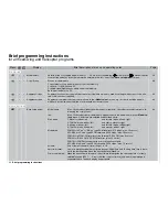
Base setup model
Model name:
Max. 10 characters (letters, numbers, special symbols). Characters are selected from a ta-
ble using the rotary control.
Info:
Max. 15 characters per model memory. Appears next to the model name in the »
Model se-
lect«
menu. Characters are selected as described above.
Stick mode:
1: Pitch-axis, tail rotor: left
and motor / coll. pitch, roll: right
2: Motor / coll. pitch, tail rot: left
and pitch-axis, roll: right
3: Pitch-axis, roll: left
and motor / coll. pitch, tail rotor: right
4: Motor / coll. pitch, roll: left
and pitch-axis, tail rotor: right
Modulation:
PCM20 for all “mc” or “DS mc” type PCM receivers (512 steps / max. 10 servos)
SPCM20 for all “smc” type SPCM receivers (1024 steps / max. 10 servos)
PPM18 for all PPM-FM receivers to date except DS 24 FM (max. 9 servos)
PPM24 for “DS 24 FM S” PPM FM receiver (max. 12 servos)
PPM10 for PPM-FM receivers with no more than fi ve outputs
APCM24 for all “amc” type APCM receivers (1024 steps / max. 12 servos)
Autorotation:
An assigned switch activates the auto-rotation fl ight phase. This has priority over all other
fl ight phase switches and the auto-rotation C1 pos. switch.
Autorot. C1 Pos.:
Alternative method of switching to auto-rotation by setting a switching point on the C1 stick;
activated using STO. A switch is required!
Marker key:
With an assigned switch (preferably the momentary switch SW8) it is possible to set a mar-
ker in fl ight which affects all C1 stick curves. This is shown as a dotted vertical line in the
curves included in the »
Helicopter mixers
« menu.
Volume:
Vary the volume of the alarm timer, range 1 to 16.
Auto timer reset:
Yes / no determines whether all timers (except “Model time” and “Battery time”) are to be re-
set to the starting value when the transmitter is switched on.
Power on warning:
When the transmitter is turned on, the software interrogates the switched state of a freely
selectable switch (SW 1 … 8, control switch or logical switch), and a warning message is
superimposed on the basic display if appropriate.
Auto-trim:
To use “Auto-trim” all you have to do is hold the model in the desired attitude using the
sticks, then operate the selected “Auto-trim” switch - preferably the momentary switch SW8.
This action automatically corrects the trims by the requisite amount. This correction takes
66
Brief programming instructions
Display
Menu
Brief description of menu and operating notes
Page
Summary of Contents for mx-24s
Page 1: ...1...
Page 19: ...19 For your notes...
Page 35: ...35 For your notes...
Page 41: ...41 41 For your notes...
Page 57: ...57 For your notes...
Page 63: ...63 63 For your notes...
Page 69: ...69 69 For your notes...
Page 85: ...85 85 For your notes...
Page 99: ...99 For your notes...
Page 143: ...143 For your notes...
Page 191: ...191 For your notes...
Page 212: ...212 212 For your notes...
Page 213: ...213 213 For your notes...
Page 214: ...214 For your notes...
Page 216: ...216...


