24
Using the system for the fi rst time
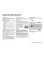
Frequency Scanner and Channel Select
Frequency scanner
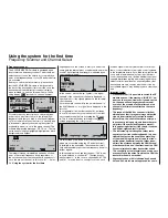
The SYNTHESIZER RF module is equipped with a
dual-conversion frequency scanner. This module en-
ables the user to scan the vicinity for occupied chan-
nels on the frequency band of your RF module before
it is activated.
Before you switch the transmitter on, please check
that the SYNTHESIZER module is fi rmly seated in
the back of the transmitter. If this is not the case, the
transmitter will switch directly to the basic display
when switched on, and the screen will show the fl a-
shing display “
C– –
” instead of a channel number
.
Model name
#01 0:30h SPCM20
H-J.Sandbrunner
10.9V
0:10h
C
0 0 0
0
Stop watch
Flight tim
0 00
0 00
:
:
For safety reasons, every time you switch the trans-
mitter on you must fi rst confi rm to the integral Syn-
thesizer module that you wish to use the set frequen-
cy. This confi rmation takes the form of a security que-
ry, intended to prevent you switching the system on
accidentally when it is set to the wrong channel. The
software displays the message: “RF off / on”. The last
set channel is initially highlighted (highlighted = black
background) and fl ashes:
C61
RF off
SCAN
---
NO
switch on
YES
Channel
The integral scanner immediately searches all chan-
nels on the current frequency band, regardless of
the set channel. If another transmitter is already acti-
ve on the pre-set channel – in this case “61” – a mes-
sage appears on the screen to alert you, and at the
same time the internal piezo sounder emits a warning
sound. The current signal strength is indicated by an
on-screen bar diagram:
C61
RF off
NO
SCAN
IN USE !!
Channel
switch on
YES
In the centre – above the “
” symbol – the signal
strength of the currently set channel is displayed, to
right and left of it the signals present on the two adja-
cent channels.
(In our example channel 61 is the lowest channel in
the 35 MHz band, so no signal bar is displayed to the
left of it.)
In our example it is clear that channel 61 is already
in use. This means that you must search for another
unoccupied channel before activating the RF modu-
le. This is accomplished by switching to the
SCAN
screen page using the rotary control:
---------------------- ----------
61 65 70 75
80
182
186
191
On this screen you will see a list of all the channels
which are accessible using the RF module current-
ly installed in the transmitter. The scanner automati-
cally and repeatedly searches the frequency band for
further signals.
In this example we can see that channel “190” is also
in use in addition to channel “61”. The signifi cantly
weaker signals – in this case on channels 62, 65, 189
and 191 – may be due to a variety of sources, such
as weak signals from very distant radio control sys-
tems, or crosstalk effects from radio control systems
in the immediate vicinity. If you think this might be the
case, walk a few metres away from the other radio
control transmitters, and observe whether the signal
strength diminishes rapidly with increasing distance.
Under certain circumstances, especially when other
transmitters are very close by, what seem to be “un-
accountable signals” may be displayed on other chan-
nels.
Important notes:
• Please note that it is possible to switch the RF
module on even if the message “IN USE !!” ap-
pears on the screen. However, if you do switch
on, then you will endanger your own model
as well as the models of other pilots due to a
channel clash (two transmitters on the same
frequency).
• The range of the
mx
-24s scanner is limited,
which means that it may not always detect the
signals from relatively distant radio control
transmitters. You should therefore not rely on
the scanner picking up signals from other mo-
del pilots if they are standing some way off;
this applies in particular if the terrain is uneven
and line-of-sight contact is limited.
• The indicated signal strength of other radio
control system transmitters depends to a con-
siderable extent on the conditions prevailing
at the model fl ying site, and also on the trans-
mitted power and aerial length of other trans-
mitters, the distance between the
mx
-24s and
other transmitters, and the direction of the
mx
-
24s aerial relative to other transmitter aerials.
The sensitivity of the integral scanner also vari-
es according to the extent to which the
mx
-24s
transmitter aerial is extended.
• At present channel 80 is followed by channels
281 and 282, which are not approved for use in
Using the system for the fi rst time
Summary of Contents for mx-24s
Page 1: ...1...
Page 19: ...19 For your notes...
Page 35: ...35 For your notes...
Page 41: ...41 41 For your notes...
Page 57: ...57 For your notes...
Page 63: ...63 63 For your notes...
Page 69: ...69 69 For your notes...
Page 85: ...85 85 For your notes...
Page 99: ...99 For your notes...
Page 143: ...143 For your notes...
Page 191: ...191 For your notes...
Page 212: ...212 212 For your notes...
Page 213: ...213 213 For your notes...
Page 214: ...214 For your notes...
Page 216: ...216...


