168
Programming examples: Fixed-wing model
time” column.
The next essential step is to assign these two fl ight
phases to a switch, which is used in fl ight to switch
between the two fl ight phases. In this case a sing-
le switch is suffi cient. However, it is important that the
switch should be within easy reach, so that you can
swiftly switch between “Motor” and “Brake” even du-
ring a landing approach, without having to let go of
one of the sticks.
The selected switch is assigned in the menu …
»Phase assignment« (page 104)
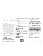
Use the rotary control to select the switch symbol be-
low “C”. After a brief press on the rotary control, con-
fi rm the desired switch, e. g. “SW 4”.
A
B
C
D
E
F
<1
>
SEL
4I
Normal
P H A S E A S S I G N M E N T
p r i o r
combi
Both switch positions, i. e. ON (
I
) and OFF ( ) are in-
itially assigned to Phase “1 normal”. Select
SEL
with
the rotary control, and give the rotary control a brief
press to activate the select list for the phases which
you have set up in the »
Phase settings
« menu. For
example, name the phase for the upper switch po-
sition “normal”, and the phase for the lower positi-
on “Landing” (or vice versa). These phase names will
now appear in all fl ight phase specifi c menus, and –
of course – also in the transmitter’s basic display.
Now move to the “
Landing
” fl ight phase and select
the “Crow” line in the sub-menu …
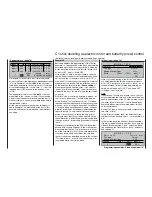
»Brake settings« (page 112 …)
AILE
Crow
B R A K E S E T T I N G S
Elevat. curve
Diff. reduct.
0%
0%
=>
… of the »
Wing mixers
« menu (see page 110). Here
you should set the desired up-travel of the ailerons
when the C1 stick (“Brake”) is moved. Now move
on to the “FLAP” column, if appropriate, in order to
set the down-travel of the fl aps (in the example abo-
ve this is suppressed). This position of the wing fl aps
is known as the “crow” or “butterfl y” setting; see also
page 119.
In the “Diff. reduction” line enter a value which corre-
sponds to the one you have entered (or intend to en-
ter) on the input side of the »
Wing mixers
« menu in
the “Aileron differential” line.
The “Elevat. curve” mixer can be set up to provide au-
tomatic suppression of the model’s pitch-trim change,
which normally occurs when ailerons are raised to act
as a landing aid. The optimum corrective values for
this must be found by test-fl ying your particular mo-
del.
If you have set everything correctly up to this point,
operating the C1 stick in the “normal” fl ight phase
simply controls the motor, whereas the motor should
be switched off in the “Landing” fl ight phase (Ser-
vo 1 to -100% in the »
Servo display
«, regardless
of “Throttle min. forward / back”, or the equivalent of
a servo travel setting which differs by 100%). In this
fl ight phase the C1 stick only controls the ailerons
and – if fi tted – the fl aps, with the neutral point at the
position of the C1 stick which corresponds to your se-
lected offset.
In the next step we have to set up the system which
controls the effect of the C1 stick on the motor.
This is achieved by moving to the menu …
»Phase settings« (page 100)
Phase 1
Phase 2
1.0s
Phase 3
0.1s
-
Phase 4
Name
SEL
SEL
Normal
1.0s
Timer
Sw. time
0.1s
SEL
-
SEL
Motor
yes
no
yes
yes
+
Landing
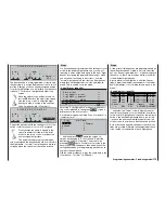
… and assigning a relevant name to “Phase 1” with a
brief press on the rotary control followed by selecting
from the list; in our example: “normal”. The asterisk (*)
in the right-hand column indicates the currently acti-
ve phase. As long as you have not assigned any pha-
se switches, this will always be Phase 1. For the sake
of our example, we will assign the name “Landing” to
“Phase 2”.
If you wish, you can assign what is known as a fl ight
phase timer to each phase in the “Timer” column, in
order to record the motor run time and also the gli-
ding times. For example, in the “normal” fl ight phase
you could assign one of the timers “Clk 1 … 3”, in or-
der to record the total motor run time via the C1 stick.
The timer is controlled by a pre-defi ned control switch
on the C1 stick. As soon as you switch to the “Lan-
ding” fl ight phase, this fl ight phase timer is automati-
cally halted, and is suppressed in the basic display.
For more details on this function please turn to page
108.
In the “Motor” column you decide the phase in which
the motor is to be controlled by the throttle / brake
stick: enter “yes / no” accordingly; this setting also de-
fi nes where the brake system – set up in the “Brake
settings” sub-menu of the »
Wing mixers
« menu – is
to be switched off (= “yes”) and on (= “no”).
Finally enter a suitable transition time in the “Switch
Summary of Contents for mx-24s
Page 1: ...1...
Page 19: ...19 For your notes...
Page 35: ...35 For your notes...
Page 41: ...41 41 For your notes...
Page 57: ...57 For your notes...
Page 63: ...63 63 For your notes...
Page 69: ...69 69 For your notes...
Page 85: ...85 85 For your notes...
Page 99: ...99 For your notes...
Page 143: ...143 For your notes...
Page 191: ...191 For your notes...
Page 212: ...212 212 For your notes...
Page 213: ...213 213 For your notes...
Page 214: ...214 For your notes...
Page 216: ...216...


