125
Program description:
Mixers
be adjusted relative to the collective pitch curve
in such a way that the correct system rotational
speed is obtained at this point.
• In the minimum position of the throttle / collecti-
ve pitch stick the throttle curve should be set up in
such a way that the motor runs at a signifi cantly
higher speed compared with the idle setting, with
the clutch reliably engaged.
In
all
fl ight phases the motor is started and
stopped using the throttle limiter (see below).
if you are used to a different radio control system
which uses two separate fl ight phases for this –
“with idle-up” and “without idle-up” – please note
that this complication is now superfl uous, and for
reasons of safety we strongly recommend that you
adopt the new technique.
Note:
The method of increasing system rotational speed be-
low the hover point is more fl exible and easier to con-
trol using the
mx
-24s program than using “idle-up” as
employed in previous
mc
radio control systems.
Ensure that the throttle limiter is closed before you
start the motor, i. e. so that the throttle can only be
adjusted within the idle range using the idle trim. Ple-
ase be sure to read the safety notes on page 131
which refer to this. If the idle is set too high when you
switch the transmitter on, you will see and hear a
clear warning!
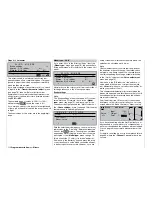
Model name
#02
H-J.Sandbrunner
9.5V
2:50h C62
0
0
0
0
Stop
Flight
0 00
0 00
:
:
Thr
too
high !
0:40h SPCM20
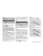
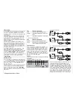
The following three diagrams show typical three-point
throttle curves for different fl ight phases, such as ho-
ver, aerobatics and 3-D fl ying.
Please note that trim values higher than +100% and
lower than -100% cannot be displayed on the screen.
Typical throttle curves for different fl ight phases:
Notes on using the “Throttle limit” function:
We strongly recommend that you make use of the
throttle limit function (»
Transmitter control adjust
«
menu, page 80). When this function is invoked, the
throttle servo is completely disconnected from the
throttle / collective pitch stick when the throttle li-
mit slider is at its bottom end-point; the motor idles
and only responds to the C1 trim. This feature enab-
les you to start the motor from within any fl ight pha-
se. Once the motor is running, move the throttle li-
miter to the opposite end-point, so that full control of
the throttle servo is returned to the throttle / collec-
tive pitch stick. It is important that the throttle limit-
er should not restrict the throttle servo at its top end-
point; you can avoid this by setting the control travel
to 125% in the »
Transmitter control adjust
« menu.
If you would like to obtain fi ner control of the thrott-
le limit control you can also use “Expo throttle limit”
(page 73). This gives you the opportunity to locate the
idle setting exactly at the centre position of the throttle
limit control, which you can easily fi nd by ear and by
eye at any time:
Set the throttle limiter to centre, and adjust the va-
lue for “EXPO throttle limit” until the motor idles per-
fectly, i. e. without moving the side-mounted proportio-
nal control from its ratcheted centre position. The mo-
tor can then be started without problem in this positi-
on. To cut the motor, slide the throttle limit control to
the bottom end-point, i. e. without even touching the
C1 cut-off trim.
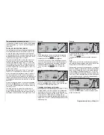
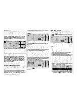
The limiting action of the throttle limiter is shown by a
horizontal bar in the throttle curve graph:
?
m
OU
T
P
U
T
--
+
1
10
0
-70%
-70%
»Normal «
Channel 1
Input
Curve
off
Point
Output
Throttle
The output signal to the throttle servo cannot be grea-
ter than the value defi ned by the horizontal bar, in this
illustration max. approx. -70%.
Tip:
If you wish to record the fl ight time of a (glow-powe-
red) model helicopter, you can assign a control switch
to the throttle limit slider, and then use this to switch a
timer on and off; see page 94.
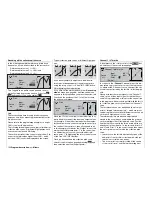
Note regarding the marker button:
If you have set the marker button in the »
Base setup
model
« menu (see page 66), a dotted vertical line
will appear in this graph when you operate the assig-
ned switch. This line indicates the position of the C1
stick the last time the switch was operated:
-30%
-30%
m
OU
T
P
U
T
--
+
1
10
0
?
»Normal «
Channel 1
Input
Curve
off
Point
Output
Throttle
Now you can move the stick in the direction of the
marker line, and place it there – or at least in the im-
mediate vicinity of another reference point – in or-
der to set the desired rotational speed at the current
hover point using the rotary control. However, if you
wish to place the hover point at the centre of the con-
–
+
–
+
–
+
L
H
Control travel
L
H
Control travel
L
H
Control travel
Hover
Aerobatic
3D flying
(curve rounded off)
Summary of Contents for mx-24s
Page 1: ...1...
Page 19: ...19 For your notes...
Page 35: ...35 For your notes...
Page 41: ...41 41 For your notes...
Page 57: ...57 For your notes...
Page 63: ...63 63 For your notes...
Page 69: ...69 69 For your notes...
Page 85: ...85 85 For your notes...
Page 99: ...99 For your notes...
Page 143: ...143 For your notes...
Page 191: ...191 For your notes...
Page 212: ...212 212 For your notes...
Page 213: ...213 213 For your notes...
Page 214: ...214 For your notes...
Page 216: ...216...


