50
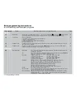
Brief programming instructions
for all fi xed-wing and helicopter programs
•
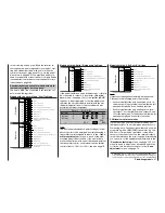
Phase settings
The name of the auto-rotation phase cannot be changed, but up to seven other fl ight phases can be programmed
and named for each model memory. The auto-rotation switch is defi ned in the »
Base setup model
« menu, the re-
maining phase switches in the »
Phase assignment
« menu.
Name:
up to ten user-defi ned phase names are available in addition to nine standard names. The ad-
ditional names can be defi ned individually in the »
General basic settings
« menu. The assig-
ned names are shown in the basic display, and in all programs which are fl ight phase specifi c.
Fl.ph.Tim.:
the switches for all these timers are assigned in the »
Flight phase timers
« menu.
Clk 1 … 3:
can be set in the »
Flight phase timers
« menu as stopwatches or alarm timers.
Lap:
in the basic display a “lap timer” appears next to the lap counter. Each press on the (momen-
tary) switch assigned in the “Lap time / elapsed time” line of the »
Flight phase timers
« menu
increases the value of the lap counter display, records the intervening lap time, and fi nally re-
starts the lap timer. Time display up to 59.9 seconds in 1/10 second increments; after 60 se-
conds in min : sec.
“Time1”:
records only those times for which the switch assigned in the “Lap time / time tab” line of the
»
Flight phase timers
« menu is “closed”. The frequency of switch operations is shown in the
basic display. This counter fi eld is highlighted as soon as the switch for the Time1 timer is
“opened”, i. e. the timer is stopped.
“Time2”:
this timer stores both the “off” and “on” times of the ON / OFF switch assigned in the “Lap time
/ time tab” line of the »
Flight phase timers
« menu, i. e. each time the switch is operated the
timing restarts and the counter is incremented by 1.
Reading out the lap counter, Time1 or Time2 in the basic display:
Set the timer switches to OFF, or stop the timer with
ESC
. The lap count or the counter of Time1 or Time2
is displayed highlighted on the screen. The individual times can now be read out using the rotary control. Fi-
nally press
CLEAR
in order to reset the counter and the times.
Sw. time:
at this point you can set a transition time (0 ... 9.9 sec) which applies when you switch
into
this phase
from any other; this provides a smooth transition between fl ight phases.
However,
when auto-rotation is selected, the delay is always zero
; the time delay set under Auto-ro-
tation is only effective when you
leave
auto-rotation.
Meaning of the symbols in the right-hand column:
indicates the phase assigned to each switch position. This is Phase 1 by default if no other swit-
ches are assigned, or if all phase switches are at the base position.
+
a switch position is provided for this phase in the »
Phase settings
« menu.
–
the phase is not in use.
102
•
•
Phase assignment
One of the eight available fl ight phases (seven for helicopters) which have been named in the »
Phase settings
«
menu can be assigned to any combination of up to six switches, termed “A” to “F”.
104
50
Brief programming instructions
Display
Menu
Brief description of menu and operating notes
Page
Summary of Contents for mx-24s
Page 1: ...1...
Page 19: ...19 For your notes...
Page 35: ...35 For your notes...
Page 41: ...41 41 For your notes...
Page 57: ...57 For your notes...
Page 63: ...63 63 For your notes...
Page 69: ...69 69 For your notes...
Page 85: ...85 85 For your notes...
Page 99: ...99 For your notes...
Page 143: ...143 For your notes...
Page 191: ...191 For your notes...
Page 212: ...212 212 For your notes...
Page 213: ...213 213 For your notes...
Page 214: ...214 For your notes...
Page 216: ...216...

