70
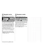
Model type
Defi ning the fi xed-wing model type
Program description:
Basic settings
M O D E L T Y P E
Tail type
Aileron/camber flaps
Brake
SEL
Offset
+100%
Input 1
Normal
1 AIL
Motor on C1
None
In this menu you defi ne the “type” of the model to be
programmed. When you do this, you also automatical-
ly defi ne all the characteristic mixers, coupling func-
tions etc. for the selected model type for subsequent
programming. Select the line with the rotary control
pressed in, and choose the required option by giving
it a brief press:
Motor on C1
“None”:
The model is a glider, with no motor.
The warning message “Throttle too
high” (see pages 22 and 59) is disab-
led, and the “Brake settings” sub-
menu in the »
Wing mixers
« menu
(see section starting on page 110) is
available without restriction.
“Thr. min back”: The idle position of the throttle / air-
brake stick (C1) is back, i. e. towards
the pilot.
The “Brake settings” sub-menu in the
»
Wing mixers
« menu (see section
starting on page 110) is only availab-
le if you have entered “no” in the cur-
rently active fl ight phase in the “Mo-
tor” column of the »
Phase settings
«
menu (see page 100).
“Thr. min front”: The idle position of the throttle / air-
brake stick (C1) is forward, i. e. away
from the pilot.
The “Brake settings” sub-menu in the
»
Wing mixers
« menu (see section
starting on page 110) is only availab-
le if you have entered “no” in the cur-
rently active fl ight phase in the “Mo-
tor” column of the »
Phase settings
«
menu (see page 100).
Notes:
•
The C1 trim only acts at the idle end of the ran-
ge, i. e. only at the “back” or “forward” end of the
stick travel. You can check the setting in the »
Ser-
vo display
« menu.
•
Cut-off trim: this special function is described on
page 34.
• If you are programming an electric-powered mo-
del and wish to control both the motor and the bra-
ke system (set in the “Brake settings” sub-menu
of the »
Wing mixers
« menu) using the C1 stick,
then set “Throttle min. forward / back” and the bra-
ke offset to suit your preferences, and then conti-
nue reading in the “Motor column” section in the
»
Phase settings
« menu on page 100.
Tail type
“normal”:
By far the majority of fi xed-wing mo-
del aircraft have a “normal tail”. For
example, this includes all powered
models and gliders with a cruciform
tail (cross-tail) in which each of the
functions elevator, rudder and thrott-
le (or speed controller or airbrakes) is
operated by one servo. The softwa-
re also includes ready-made mixers
which can cope with a maximum of
two aileron servos and four fl ap ser-
vos. See the section starting on page
110.
“V-tail”:
The elevator and rudder controls are
operated by two control surfaces set
in a V-shape, each controlled by a
separate servo. The two-way coup-
ling function for the rudder and ele-
vator control systems is automatical-
ly carried out by the transmitter soft-
ware. The ratio of rudder to eleva-
tor travel can be adjusted using the
»
Dual Rate / Expo
« menu (page 86),
while the servo travels can be adjus-
ted in the »
Servo adjustment
« menu
(page 74).
If you also wish to be able to apply
differential to the rudder travels, then
the V-tail should be set up using the
»
Dual mixers
« menu (see page 144)
instead. In this case it is essential
to set the tail type to “normal” at this
point.
“Delt/fl .wing”:
The standard arrangement is for aile-
ron and elevator control to be achie-
ved by means of one left and one
right “aileron servo”. However the re-
vised »
Wing mixers
« menu (see
page 110) also provides a convenient
method of programming deltas and
fl ying wings with more than two wing-
mounted control surfaces; this is ac-
cessed under the “Delta / fl ying wing”
model type.
Important note:
If your model has more than two wing
fl aps, It is ESSENTIAL to program
the elevator function by setting the
“El
Fl” line of the “Multi-fl ap menu”
of the »
Wing mixers
« menu; see the
centre column on page 117.
“2 EL Sv 3+8”: This option is designed for model
aircraft with two elevator servos.
When you move the elevator stick,
the servo connected to receiver out-
put 8 moves in parallel with the stan-
Summary of Contents for mx-24s
Page 1: ...1...
Page 19: ...19 For your notes...
Page 35: ...35 For your notes...
Page 41: ...41 41 For your notes...
Page 57: ...57 For your notes...
Page 63: ...63 63 For your notes...
Page 69: ...69 69 For your notes...
Page 85: ...85 85 For your notes...
Page 99: ...99 For your notes...
Page 143: ...143 For your notes...
Page 191: ...191 For your notes...
Page 212: ...212 212 For your notes...
Page 213: ...213 213 For your notes...
Page 214: ...214 For your notes...
Page 216: ...216...


