93
Program description:
Transmitter controls
?
«Hover »
Input
Curve
off
Point
Output
Channel 1 C U R V E
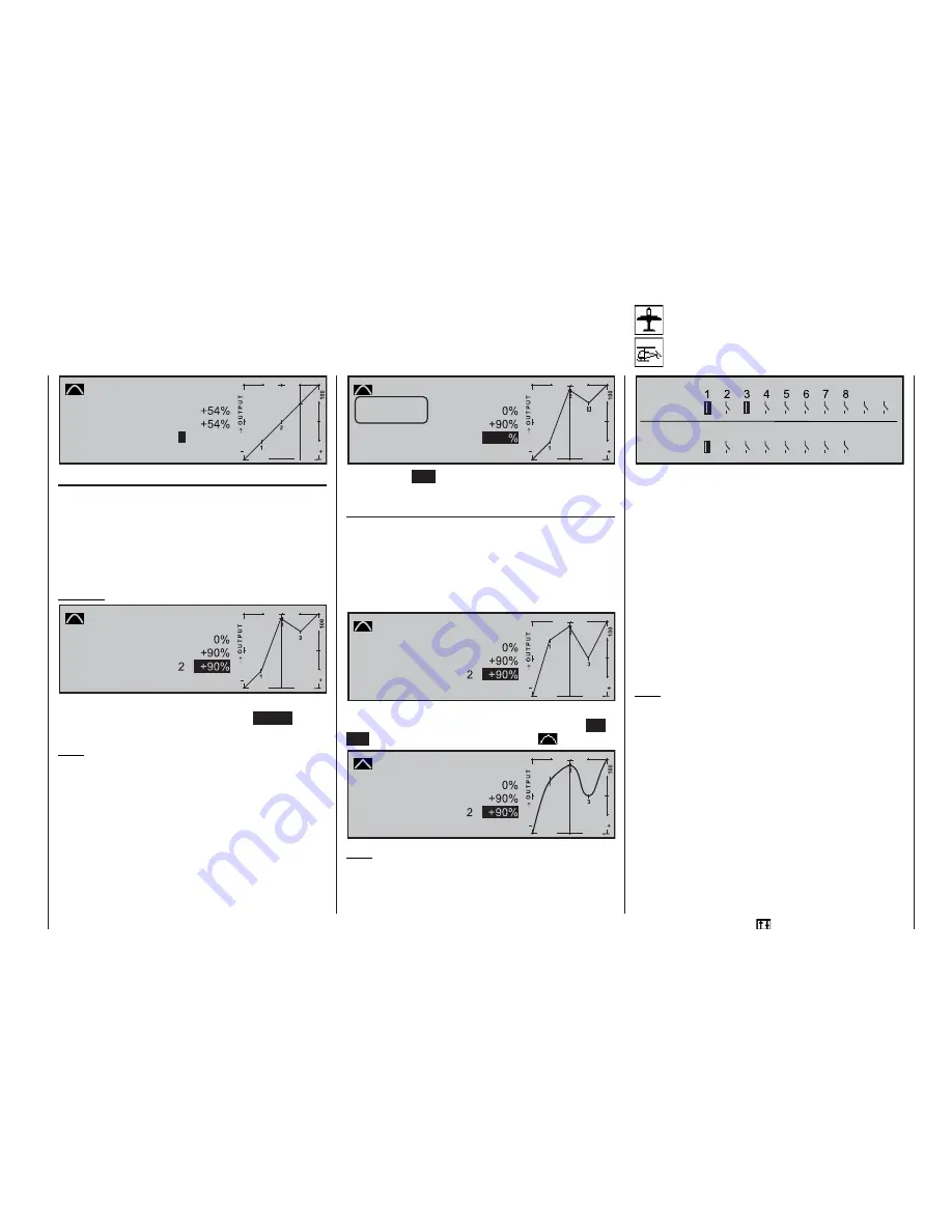
Changing the reference point values
Move the stick to the reference point “L (low), 1 ... 6
or H (high)” which you wish to change. The number
and the current curve value of this point are displayed
on the screen. You can now use the rotary control to
change the momentary curve value in the highlighted
fi eld within the range -125% to +125%, without affec-
ting the adjacent reference points.
Example:
«Hover »
Input
Curve
off
Point
Output
Channel 1 C U R V E
As an example the reference point “2” has been set to
+90% in this screen-shot. Pressing the
CLEAR
button
erases the reference point.
Note:
If the stick is not set to the exact reference point, ple-
ase note that the percentage value in the “Output” line
always refers to the actual momentary stick position.
Alternatively you can skip straight to reference points
that have already been set in the upward or downward
direction by turning the rotary control when pressed
in; the number of the addressed point 1 … max. 6 is
always highlighted in the graph. When you release the
rotary control, the reference point can then be altered
as described previously, completely independently of
the position of the transmitter control.
3
+55
«Hover »
Input
Curve
off
Point
Output
Channel 1 C U R V E
Trim Point
Quit = ESC
Pressing the
ESC
button concludes this trim point
function.
Rounding off the Channel 1 curve
In the following example the reference points have
been set as follows, as described in the previous sec-
tion:
Reference point value 1 to +50%,
Reference point value 2 to +90%, and
Reference point value 3 to +0%.
«Hover »
Input
Curve
off
Point
Output
Channel 1 C U R V E
This “jagged” curve profi le can be rounded off auto-
matically simply by pressing a button. Press the
EN-
TER
button next to the “curve symbol”
:
«Hover »
Input
Curve
on
Point
Output
Channel 1 C U R V E
Note:
The curves shown here are only for demonstration
purposes, and by no means represent realistic thrott-
le / collective pitch curves.
Switch display
Display of the switch settings
9 10
G1 G2 G3 G4 G5 G6 G7 G8
Switch
Contrl
Switch
This function enables you to check the various switch
functions, and provides an overview of the switches
installed in your transmitter, together with the pro-
grammable control switches.
When you operate a switch, the number of that switch
becomes obvious on-screen because its normal OFF
symbol changes to an ON symbol, and vice versa.
Closed (ON) switches are always highlighted, i. e.
on a black background, to make them more readily
noticeable.
The same applies to the control switches G1 … G8:
when you operate the associated transmitter control
(i. e. the one already assigned in the »
Control swit-
ches
« menu) you can immediately see the number of
the control switch and the direction of switching.
Note:
The numbering 1 to 10 of the external switches
shown here equates to the numbers printed on the
transmitter case. However, the switch numbers have
no signifi cance at all for the purpose of programming.
Summary of Contents for mx-24s
Page 1: ...1...
Page 19: ...19 For your notes...
Page 35: ...35 For your notes...
Page 41: ...41 41 For your notes...
Page 57: ...57 For your notes...
Page 63: ...63 63 For your notes...
Page 69: ...69 69 For your notes...
Page 85: ...85 85 For your notes...
Page 99: ...99 For your notes...
Page 143: ...143 For your notes...
Page 191: ...191 For your notes...
Page 212: ...212 212 For your notes...
Page 213: ...213 213 For your notes...
Page 214: ...214 For your notes...
Page 216: ...216...


