121
121
Program description:
Mixers
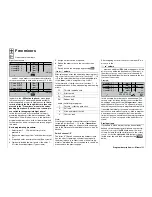
Aileron 2
4 rudder
SEL
=>
0%
0%
0%
Multi-flap menu
Brake settings
Aileron
Flaps
=>
2–>4 rudder
6–>3 elevator
W I N G M I X E R S
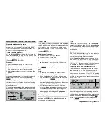
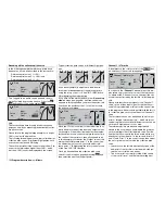
This mixer causes the rudder to “follow” automatically
when an aileron command is given.
Select the
SEL
fi eld, and give the rotary control a
brief press. You can now set the desired value for this
function using the rotary control. The mixer direction
must be chosen to ensure that the rudder moves in
the direction of the up-going aileron.
If you assign a switch to this function in the right-hand
column, you will be able to switch the mixer on and off
in fl ight.
The available range of values is -150% to +150%,
while pressing
CLEAR
resets the value to 0%.
This setting can only be carried out symmetrically re-
lative to the neutral point of the aileron stick.
A value of around 50% is generally an excellent star-
ting point.
Flaps 6
3 elevator
SYM
0%
0%
0%
ASY
Multi-flap menu
Brake settings
Aileron
Flaps
=>
=>
2–>4 rudder
6–>3 elevator
W I N G M I X E R S
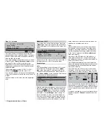
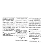
This mixer is used to set elevator (pitch-trim) compen-
sation when a fl ap command is given. Symmetrical or
asymmetrical settings relative to the neutral point of
the fl ap control are possible.
The available range of values is -150% to +150%,
while pressing
CLEAR
resets the value to 0%.
If you have assigned a transmitter control or a switch
in the »
Transmitter control adjust
« menu, as descri-
bed under “
Fl
” on page 118, then the sameone
also affects this mixer. In this case the settings are
entered in the same manner.
This mixer can also be switched on and off if a switch
is assigned to it.
Tips for operating airbrakes:
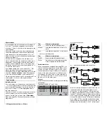
AIL
FL
FL
AIL
Servo 1
Servo 9
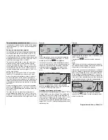
• If you have installed a servo for operating conven-
tional wing-mounted airbrakes in addition to the ai-
leron and fl ap servos, the simplest method of con-
trolling it is to connect it to that receiver output
whose input you have selected for the brake func-
tion, i. e. either 1, 7, 8 or 9 – if it is not already in
use for some other purpose. If this is not possible,
then the alternative is to set up a free mixer which
links your chosen brake control channel to the air-
brake servo.
• To operate two airbrake servos it is best to leave
one servo at Output 1, and to connect the second
servo to any vacant output, for example, output 9,
which is not fl ight phase specifi c. Now move to the
»
Transmitter control adjust
« menu (see page
78) and assign this to transmitter control 1 (usually
correct) – see screen-shot.
Cnt.
0%
ASY
SYM
SEL
SEL
ASY
SYM
0%
0%
0%
+100%+100%
+100%+100%
+100%+100%
+100%+100%
0.0 0.0
0.0 0.0
0.0 0.0
0.0 0.0
Input
Input
Input
Input
12
11
10
9
libre
1
libre
libre
offset
–
–time+
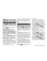
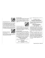
The settings for offset, travel etc. should be left
at their default values. You can reassure yourself
that this works by calling up the »
Servo display
«
menu, which you access by pressing the
HELP
button with the rotary control pressed in:
1
+100%
2
0%
3
0%
4
0%
5
0%
6
0%
7
0%
8
0%
9
+100% 10
0%
11
0% 12
0%
If, for whatever reason, this relatively simple ar-
rangement should not prove to be feasible, then
an alternative solution is to use two free mixers,
perhaps using the »
MIX only channel
« menu -
see page 142.
However, in either case the airbrake travels have
to be fi ne-tuned in the »
Servo adjustment
« menu
(see page 74).
Summary of Contents for mx-24s
Page 1: ...1...
Page 19: ...19 For your notes...
Page 35: ...35 For your notes...
Page 41: ...41 41 For your notes...
Page 57: ...57 For your notes...
Page 63: ...63 63 For your notes...
Page 69: ...69 69 For your notes...
Page 85: ...85 85 For your notes...
Page 99: ...99 For your notes...
Page 143: ...143 For your notes...
Page 191: ...191 For your notes...
Page 212: ...212 212 For your notes...
Page 213: ...213 213 For your notes...
Page 214: ...214 For your notes...
Page 216: ...216...

