17
Operating notes
Changing the frequency band and spot frequency
The
mx
-24s transmitter is fi tted as standard with a
PLL-SYNTHESIZER RF module. The spot frequen-
cy (channel) is selected using the rotary control, i. e.
plug-in crystals are no longer required at the transmit-
ter.
The Synthesizer module also features
an integral
dual-conversion frequency scanner which is used to
check whether your preferred channel is already in
use or not; it can also be employed to determine the
vacant channels on your particular frequency band.
A detailed description of the method of using the
Synthesizer module and selecting spot frequencies
is found on pages 24 and 25 in the section entitled
“Using the transmitter for the fi rst time – frequency
scanner and channel selection”.
The set spot frequency is displayed on-screen. A se-
curity system prevents the transmitter radiating an
RF signal when initially switched on. The RF module
must fi rst be activated in the software, which provides
an additional gain in safety.
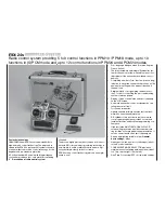
At present two separate transmitters are available: for
the 35 / 35B MHz band and the 40 / 41 MHz band:
Transmitters alone:
Order No.
4730.77
for the 35 / 35B* MHz band
Order No.
4748.77
for the 40 / 41* MHz band
* Channels 281 and 282 on the 35 MHz band, and all channels
on the 41 MHz band, are not approved for use in Germany; see
also the Frequency Table on page 206. The same table shows
which channels are approved for use with the various types of
model, i. e. model aircraft, model boats and RC cars.
The channels approved for use in individual countries
are shown in the Frequency Table on page 206 (infor-
mation not guaranteed).
The receiver must be operated on the same channel
and the same frequency band as the transmitter.
It is possible to use this transmitter to control any
GRAUPNER
PLL Synthesizer receiver as well as ear-
lier crystal-controlled
GRAUPNER
receivers, provided
that they are compatible with the transmitter modes
PCM20, SPCM20, PPM18 or PPM24.
If you wish to use earlier crystal-controlled
GRAUP-
NER
receivers, it is essential to use genuine
GRAUP-
NER
FMsss plug-in crystals designed for the appro-
priate frequency band (see page 206). The receiver
crystal is marked “R” (Receiver), and should be inser-
ted fi rmly into the opening in the receiver.
Important note:
The RF Synthesizer module is connected to the
mx
-
24s transmitter by means of two sockets. If the RF
module is not plugged in correctly, the transmitter will
switch directly to the basic display when switched on.
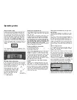
The screen will then display the fl ashing message
“
C––
” instead of a channel number, indicating that the
RF module is not ready for use.
#01 0:00h SPCM20
10.9V
0:05h
C - -
0 0 0
0
Stop watch
Flight tim
0 00
0 00
:
:
Changing the frequency band
If you wish to switch from the 35 / 35B MHz band to
the 40 / 41 MHz band or vice versa, all you have to
do is replace the SYNTHESIZER RF module in the
transmitter:
Order No.
3853.35
for the 35 / 35B MHz band
Order No.
3853.40
for the 40 / 41 MHz band
Summary of Contents for mx-24s
Page 1: ...1...
Page 19: ...19 For your notes...
Page 35: ...35 For your notes...
Page 41: ...41 41 For your notes...
Page 57: ...57 For your notes...
Page 63: ...63 63 For your notes...
Page 69: ...69 69 For your notes...
Page 85: ...85 85 For your notes...
Page 99: ...99 For your notes...
Page 143: ...143 For your notes...
Page 191: ...191 For your notes...
Page 212: ...212 212 For your notes...
Page 213: ...213 213 For your notes...
Page 214: ...214 For your notes...
Page 216: ...216...

