117
117
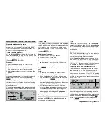
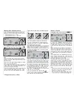
Program description:
Mixers
Model type: “2 AIL 4 FL”
If you have connected the servos to the receiver in
the order described in the section starting on page
37, and have selected them as shown in the »
Model
type
« menu (see page 70), then the abbreviations
“AIL”, “FL” and “FL2” refer to the wing fl aps as shown
below:
AIL
left
FL
left
FL2
left
FL2
right
FL
right
AIL
right
Since the selection of “2 AIL 4 FL” represents the
maximum possible number of wing-mounted servos,
all the set-up options for all the wing fl aps are now
available without restriction in the Wing mixer menu
and its sub-menus.
+100%
0%
0%
0%
0%
0% 0% 0%
0%
0%
0% +100%+100%
0% 0% 0%
0%
SEL
SEL
SEL
+100%
FL2
0%
+100%+100%
0%
0%
0%
AI
Ail–tr
Diff.
Fl.pos
FL
El–>Fl
AILE
FLAP
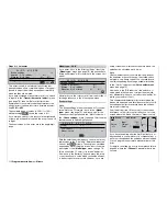
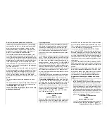
Models of the Delta / Flying wing type with more
than two wing fl aps
If you have selected the “Delta / fl ying wing” tail type,
and selected the number of wing fl aps in the “Aile-
rons / fl aps” line of the »
Model type
« menu as sta-
ted in the description at that point, then normally the
two ailerons will not move when you give an elevator
command, and nor will the inner fl aps (FL) and FL2 (if
present). The reason for this is that the default mixer
input for all wing fl aps is 0%, as can be seen in the
“El
Fl” mixer in the multi-fl ap menu shown here:
+100%
0%
0%
0%
0%
0% 0% 0%
0%
0%
0% +100%+100%
0% 0% 0%
0%
SYM
+100%
0%
+100%+100%
0%
0%
0%
ASY
SYM
ASY
SYM
ASY
FL2
AILE
FLAP
AI
Ail–tr
Diff.
Fl.pos
FL
El–>Fl
You must therefore start by defi ning the desired ele-
vator effect in the “El
Fl” line. Please note that it is
essential to set the correct direction of operation of
the elevators.
Note:
The “Brake settings” sub-menu (see next double
page) is also suitable for setting up the butterfl y
(crow) function with deltas and fl ying wing models.
However, the fi ne-tuning of the travels of the fl ap pairs
AIL, FL and (if present) FL2 should be carried out in
such a way that the pitch-trim moments caused by
one pair of fl aps compensate for the opposite mo-
ments caused by the other pair of fl aps. For examp-
le, the “up” effect of ailerons when defl ected up is
compensated by a corresponding “down” effect of the
camber-changing fl aps when they are lowered.
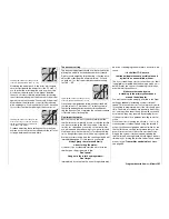
Multi-fl ap menu
“
Al
”
(Aileron
fl ap)
(suppressed if “2 AIL 1 FL” is selected)
+100%
0%
0%
0%
0%
0% 0% 0%
0%
0%
0% +100%+100%
0% 0% 0%
0%
SEL
SEL
SEL
+100%
FL2
0%
+100%+100%
0%
0%
0%
AI
Ail–tr
Diff.
Fl.pos
FL
El–>Fl
AILE
FLAP
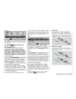
In this line you can set the extent in percentage terms
to which the pair of wing fl aps “FLAP”, and – if pre-
sent – “FL2”, follow when an aileron command is gi-
ven. This value can be entered separately for each
fl ight phase. (In the “AILE” column it is also possible
to adjust the defl ection of the ailerons.)
In all of the (maximum) three columns the parameters
can be varied within the range -150% to +150% after
the appropriate value fi elds have been activated.
Pressing
CLEAR
resets altered entries to the default
values, as shown in the screen-shot above.
Please note that fl aps should not follow the (mecha-
nical) travel of the ailerons to more than about 50%. It
also makes sense to set the travel of the inboard fl aps
(FL2) to an even smaller value.
“Ail-tr”
(Aileron trim
fl ap)
(suppressed if “2 AIL 1 FL” is selected)
+100%
0%
0%
0%
0%
0% 0% 0%
0%
0%
0% +100%+100%
0% 0% 0%
0%
SEL
SEL
SEL
+100%
0%
+100%+100%
0%
0%
0%
FL2
AILE
FLAP
AI
Ail–tr
Diff.
Fl.pos
FL
El–>Fl
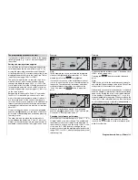
In this line you can set the extent in percentage terms
Summary of Contents for mx-24s
Page 1: ...1...
Page 19: ...19 For your notes...
Page 35: ...35 For your notes...
Page 41: ...41 41 For your notes...
Page 57: ...57 For your notes...
Page 63: ...63 63 For your notes...
Page 69: ...69 69 For your notes...
Page 85: ...85 85 For your notes...
Page 99: ...99 For your notes...
Page 143: ...143 For your notes...
Page 191: ...191 For your notes...
Page 212: ...212 212 For your notes...
Page 213: ...213 213 For your notes...
Page 214: ...214 For your notes...
Page 216: ...216...


