150
Teacher/pupil
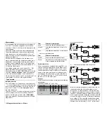
Connecting two transmitters for Trainer mode (teacher / pupil) operations
T E A C H E R / P U P I L
P
T
C1
AI EL RU 05 06 07 08 09 10
The
mx
-24s transmitter features a DSC socket on
the rear of the case as standard. This is suitable for
connecting a fl ight simulator and the diagnosis lead,
Order No.
4178.1
(as described on page 18), and
also for integrating the transmitter in a Trainer (tea-
cher / pupil) system. The transmitter can also be used
in “Teacher” mode if it is fi tted with the optional Tea-
cher / PC module, Order No.
3290.22
; see Appendix.
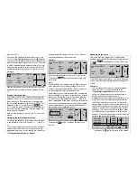
Teacher transmitter settings
Up to ten control functions of the Teacher transmitter
“T” can be transferred to the Pupil transmitter “P” eit-
her individually or in any combination.
The bottom line of the screen, marked “T”, indicates
the number of the transmitter control which is assig-
ned to inputs 1 … 4 (stick functions) and to one of the
inputs 4 … 10 in the »
Transmitter control adjust
«
menu.
Use the rotary control to select the channels 1 to 10
which you wish to transfer, and press the rotary con-
trol briefl y to switch between “T (Teacher)” ( ) and “P
(Pupil)” ( ) modes. If, for instance, you wish to transfer
control of the four functions on the two dual-axis stick
units plus the fl aps to the pupil, and the fl aps are con-
trolled on the Teacher transmitter by the right-hand
side-mounted proportional control “CTRL 9” assigned
to “Input 6”, then you should switch transmitter control
numbers 1 to 4 and 9 from “T” to “P”.
P
T
01
02 03 04 05 06 07 08 09 10
T E A C H E R / P U P I L
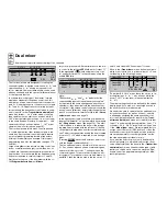
Note:
The screen-shot on top of the left-hand column shows
the display for the “Fixed-wing” model type; the shot
above shows the “Helicopter” model type. The only
difference lies in the designations of the four functions
controlled by the two dual-axis stick units.
To be able to transfer control to the pupil you must as-
sign a Trainer switch; this is carried out on the right-
hand side of the screen. We advise the use of the
momentary switch SW 8, as this allows you to regain
control at the Teacher transmitter without any delay,
just by releasing it.
P
T
01
02 03 04 05 06 07 08 09 10
8
T E A C H E R / P U P I L
The model to be controlled by the pupil
must be
programmed completely
in one of the Teacher
transmitter’s model memories, i. e. with all its func-
tions including trims and any mixer functions. The pro-
gramming must be carried out at the Teacher trans-
mitter because it is this unit which actually controls
the model, even in Pupil mode. For this reason the
Teacher transmitter can be operated in any of the ty-
pes of modulation available.
The
mx
-24s transmitter should now be connected to
the Pupil transmitter via the DSC socket and the ap-
propriate Trainer lead.
PLEASE NOTE: YOU MUST
ALWAYS SWITCH THE TRANSMITTER ON FIRST,
AND ONLY THEN PLUG IN THE CONNECTING
LEAD.
If you do not keep to this sequence, you will
have no means of activating the RF module.
However, if you use the Teacher / PC module, Order
No.
3290.2
, the order in which you connect the sys-
tem is of no signifi cance.
At the end of this chapter you will fi nd a summary of
the connecting leads required; more information is in-
cluded in the Appendix on page 204.
Pupil transmitter set-up
The following transmitters can be used as the Pu-
pil unit: Graupner/JR D14, FM414, FM4014, FM6014,
mc
-10,
mc
-12,
mx
-12,
mc
-14,
mc
-15,
mc
-16,
mx
-16s,
mc
-16/20,
mc
-17,
mc
-18,
mc
-19,
mc
-
20,
mc
-22,
mc
-22s,
mx
-22,
mc
-24 and
mx
-24s,
with four to ten control functions.
The Pupil transmitter should be connected to the Tea-
cher transmitter using the appropriate lead; see the
following double page and page 204 of the Appendix.
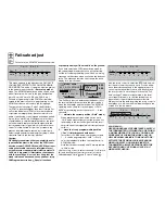
Important:
The Pupil transmitter MUST ALWAYS be set to
operate in PPM mode, regardless of the modulati-
on set on the Teacher transmitter: either PPM18 (1
… 9) or PPM24 (1 … 10), according to the number
of channels to be transferred. However, if the Pu-
pil transmitter is connected using its DSC socket,
you must ALWAYS leave the Pupil transmitter’s
On / Off switch at the “OFF” position, because this
is the only setting in which the transmitter modu-
le does not broadcast an RF signal even with the
DSC lead plugged in. In this case the transmitter’s
basic screen shows the message “DSC” instead
of the selected transmitter channel:
150
Program description:
Special functions
Summary of Contents for mx-24s
Page 1: ...1...
Page 19: ...19 For your notes...
Page 35: ...35 For your notes...
Page 41: ...41 41 For your notes...
Page 57: ...57 For your notes...
Page 63: ...63 63 For your notes...
Page 69: ...69 69 For your notes...
Page 85: ...85 85 For your notes...
Page 99: ...99 For your notes...
Page 143: ...143 For your notes...
Page 191: ...191 For your notes...
Page 212: ...212 212 For your notes...
Page 213: ...213 213 For your notes...
Page 214: ...214 For your notes...
Page 216: ...216...

