Chapter 5 Trial Run and Tuning Procedure
5-18
Revision June 2010
NOTE
1)
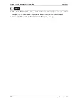
Parameters P2-44 and P2-46 are used to set notch filter attenuation rate. If the resonance can
not be suppressed when the setting values of P2-44 and P2-46 are set to 32bB (the maximum
value), please decrease the speed loop frequency response. After setting P2-47, the users can
check the setting values of P2-44 and P2-46. If the setting value of P2-44 is not 0, it indicates
that one resonance frequency exists in the system and then the users can read P2-43, i.e. the
frequency (unit is Hz) of the resonance point. When there is any resonance point in the system,
its information will be shown in P2-45 and P2-46 as P2-43 and P2-44.
2)
If the resonance conditions are not improved when P2-47 is set to 1 for over three times,
please adjust notch filters (resonance suppression parameters) manually to or eliminate the
resonance.
Summary of Contents for ASD-B2-0121-B
Page 1: ......
Page 13: ...Table of Contents xii Revision June 2010 This page intentionally left blank...
Page 17: ...Chapter 1 Unpacking Check and Model Explanation 1 4 Revision June 2010 ECMA Series Servo Motor...
Page 87: ...Chapter 4 Display and Operation 4 12 Revision June 2010 This page intentionally left blank...
Page 131: ...Chapter 6 Control Modes of Operation 6 22 Revision June 2010 Time Domain...
Page 267: ...Chapter 8 MODBUS Communications 8 18 Revision June 2010 This page intentionally left blank...
Page 271: ...Chapter 9 Maintenance and Inspection 9 4 Revision June 2010 This page intentionally left blank...
Page 291: ...Chapter 11 Specifications 11 8 Revision June 2010 11 3 Servo Motor Speed Torque Curves...


